
email: calmansys@yahoo.com
Competency Based Training on Instrumentation
What is Instrumentation?
Measurement and control
in a Processing Plant
Basic Elements of Instrumentation:
Sensors and Transmitters
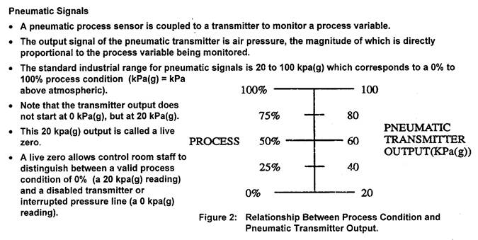
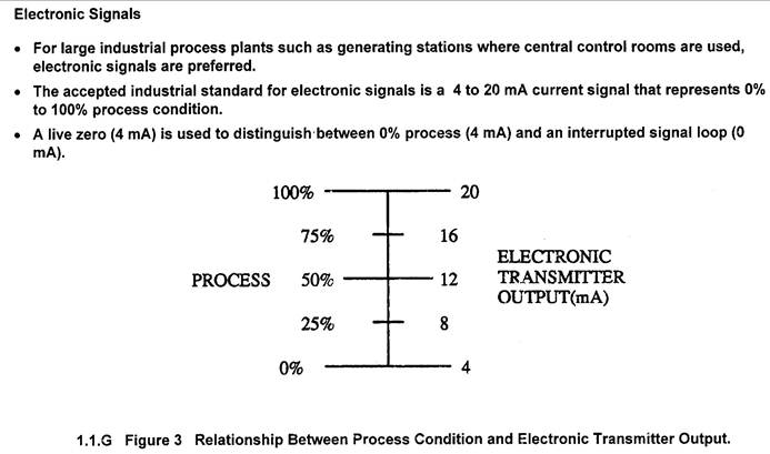
Signal Transmission Standards
Pneumatic, Electronic, Digital (Hart, Fieldbus)
Piping and Instrumentation Diagrams
Controllers and Final Control Elements
PID controllers Control Valves

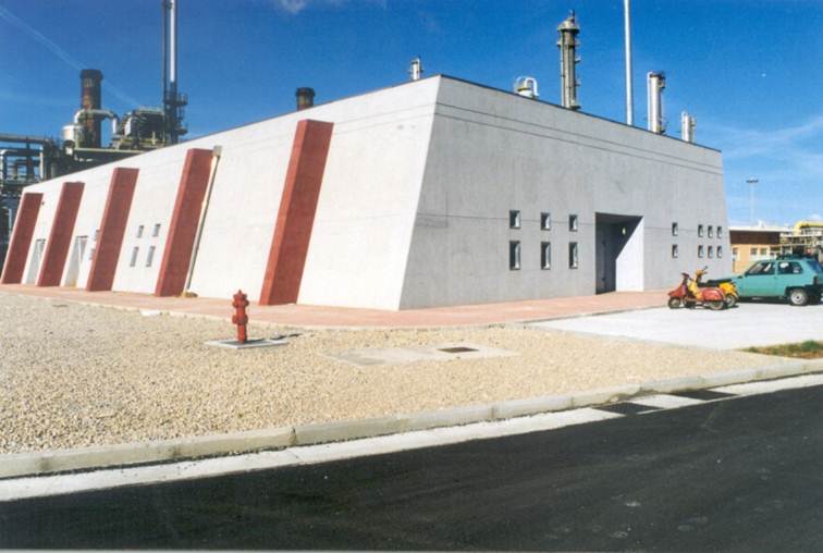
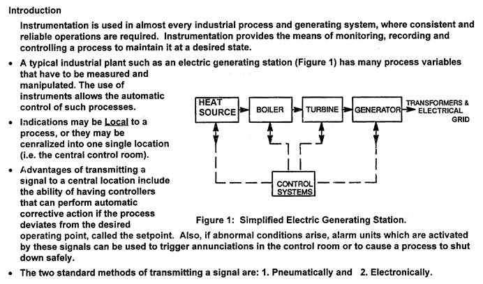
Control Building

Instruments installed on pipes, vessels and equipment measure flow, pressure,temperature
and level convert them to analog signals and send them to a central control room.

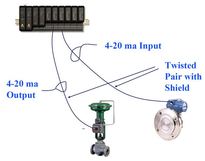
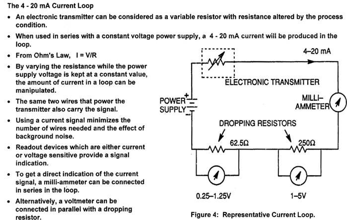
Signalling between instruments and the central control room is via two wire
electronic analog 4 to 20 mA or pneumatic 3 to 15 psi signal
The principle of this flow measurement is the pressure drop across the OrificePlate is proportional to the flow rate. The pressure drop is measured by a differentialPressure transmitter and converted to flow indication.
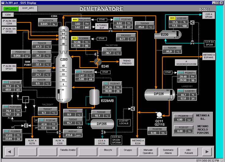
In the control room, the analog signals are converted to digital for processing and display at the
DCS operator graphics workstation. The process values are displayed along with the graphic
representation of the equipment. An abnormal process value will trigger an alarm.
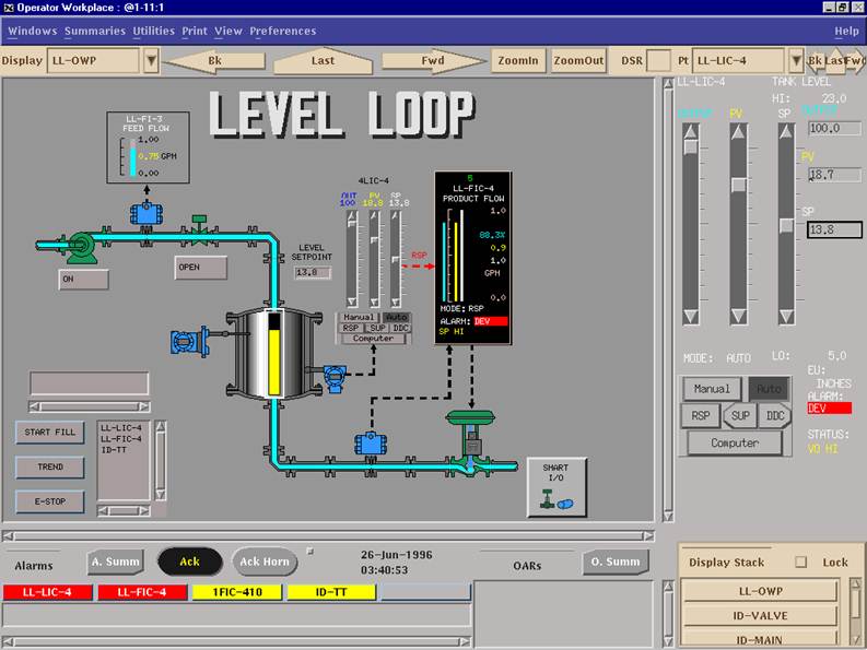

Controllers receive these values and process them, send signals to the field mounted control valves,
dampers or motors to keep these values at some desired operating point
Signal Transmission
A Simple Tank Temperature Control Loop
The temperature of the liquid in the tank is controlled by regulating the flow
of the heating medium to the tank jacket by varying the Temperature Control Valve opening.
Tank temperature is measured by a thermocouple and transmitted to the controller where it
is compared to the desired value or setpoint. If they are not equal, depending on the size of
the deviation, the controller will change the valve opening and hence, the flow of the heating
medium and the tank temperature. This process where the effect of the control action is fed
back to the controller is called the “feedback control loop.”
With the indicated process conditions, what are the values for:
1. analog signal from the transmitter to A/D converter?
2. Digital to analog converter to I/P?
3. I/P to control valve?
Answer
Loopcheck usually starts at the transmitter and ends with the control valve
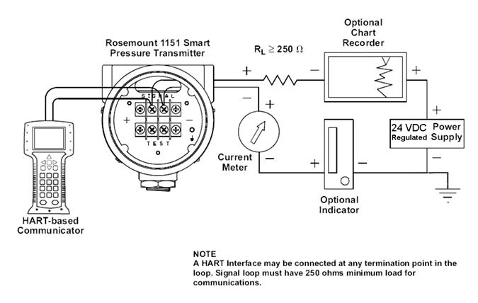
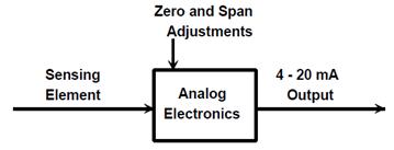
Bench calibration requires a 24VDC regulated power supply. Connect the indicators
in series, observing the correct polarity. For small errors adjust the zero and span
potentiometers. To re-range or reconfigure the transmitter a HART- based Communicator
is required.

HART Protocol supports two way digital communications for process measurement and control devices
Allows remote process variable interrogation, parameter setting and diagnostics.
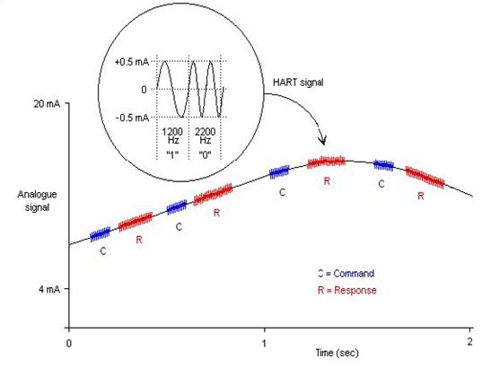
Communication signal is superimposed on top of the 4-20ma signal from 2-wire or 4-wire transmitters
Digital or analog value may be used for measurement and control.
Calibrating HART Transmitters
HART Fundamentals
HART is an acronym for Highway Addressable Remote Transducer developed by
Rosemount in 1986. Rosemount made HART an open protocol, many manufacturers
incorporated it into their products. It has now become the standard for field communication with
instruments. HART products generally fall into one of three categories:
Field Devices,
Host Systems, and
Communication Support hardware.
Field Devices include transmitters, valves, and controllers.
There are HART transmitters for almost any standard process measurement including
pressure, temperature, level, flow, and analytical (pH, ORP, density).

Host Systems range from small handheld communicators to PC based maintenance management
software to large scale distributed control systems.
Just prior to the first box, the instrument's microprocessor measures some electrical property that
is affected by the process variable of interest. The measured value may be millivolts, capacitance,
reluctance, inductance, frequency, or some other property. However, before it can be used by the
microprocessor, it must be transformed to a digital count by an analog to digital (A/D) converter.
In the first box, the microprocessor must rely upon some form of equation or table to relate the raw
count value of the electrical measurement to the actual property (PV) of interest such as temperature,
pressure, or flow.
The principle form of this table is usually established by the manufacturer, but most HART instruments
include commands to perform field adjustments. This is often referred to as a sensor trim. The output
of the first box is a digital representation of theprocess variable. When you read the process variable
using a communicator, this is the value that you see.
The second box is strictly a mathematical conversion from the process variable to the equivalent
milliamp representation. The range values of the instrument (related to the zero and span values)
are used in conjunction with the transfer function to calculate this value. Although a linear transfer
function is the most common, pressure transmitters often have a square root option. Other special
instruments may implement common mathematical transformations or user defined break point tables.
The output of the second block is a digital representation of the desired instrument output. When you
read the loop current using a communicator, this is the value that you see. Many HART instruments
support a command which puts the instrument into a fixed output test mode.
This overrides the normal output of the second block and substitutes a specified output value.
The third box is the output section where the calculated output value is converted to a count value
that can be loaded into a digital to analog converter. This produces the actual analog electrical signal.
Once again the microprocessor must rely on some internal calibration factors to get the output correct.
Adjusting these factors is often referred to as a current loop trim or 4-20 mA trim.
HART Calibration Requirements
Based on this analysis, you can see why a proper calibration procedure for a HART instrument is
significantly different than for a conventional instrument. The specific calibration requirements
depend upon the application. If the application uses the digital representation of the process
variable for monitoring or control, then the sensor input section must be explicitly tested and
adjusted. Note that this reading is completely independent of the milliamp output, and has nothing
to do with the zero or span settings. The PV as read via HART communication
continues to be accurate even when it is outside the assigned output range. For example, a range 2
inches of water, and then apply a pressure of 150 inches of water, the analog output will saturate at
just above 20 milliamps.
However, a communicator can still read the correct pressure. If the current loop output is not used (that is the transmitter is used as a digital only device), then the input section calibration is all that
is required. If the application uses the milliamp output, then the output section must be explicitly
tested and calibrated. Note that this calibration is independent of the input section, and again, has
Calibrating the Input Section
The same basic multiple point test and adjust technique is employed, but with a new definition for
output. To run a test, use a calibrator to measure the applied input, but read the associated output
(PV) with a communicator. Error calculations are simpler since there is always a linear relationship
between the input and output, and both are recorded in the same engineering units.
In general, the desired accuracy for this test will be the manufacturer's accuracy specification. If the
test does not pass, then follow the manufacturer's recommended procedure for trimming the input
section. This may be called a sensor trim and typically involves one or two trim points.
Pressure transmitters also often have a zero trim, where the input calculation is adjusted to read
exactly zero (not low range). Do not confuse a trim with any form of re-ranging or any procedure
that involves using zero and span buttons.
Calibrating the Output Section
Again, the same basic multiple point test and adjust technique is employed, but with a new definition
for input. To run a test, use a communicator to put the transmitter into a fixed current output mode.
The input value for the test is the mA value that you instruct the transmitter to produce. The output
value is obtained using a calibrator to measure the resulting current. This test also implies a linear
relationship between the input and output, and both are recorded in the same engineering units
(milliamps). The desired accuracy for this test should also reflect the manufacturer's accuracy
specification.If the test does not pass, then follow the manufacturer's recommended procedure for
trimming the output section.
This may be called a 4-20 mA trim, a current loop trim, or a D/A trim. The trim procedure should
require two trim points close to or just outside of 4 and 20 mA. Do not confuse this with any form of
re-ranging or any procedure that involves using zero and span buttons.
Testing Overall Performance
After calibrating both the Input and Output sections, a HART transmitter should operate correctly.
The middle block in Figure 4 only involves computations. That is why you can change the range,
units, and transfer function without necessarily affecting the calibration. Notice also that even if
the instrument has an unusual transfer function, it only operates in the conversion of the input
value to a milliamp output value, and therefore is not involved in the testing or calibration of either
the input or output sections.If there is a desire to validate the overall performance of a HART
transmitter, run a Zero and Span test just like a conventional instrument. As you will see in a moment,
however, passing this test does not necessarily indicate that the transmitter is operating correctly.
Effect of Damping on Test Performance
Many HART instruments support a parameter called damping. If this is not set to zero, it can have an
adverse effect on tests and adjustments. Damping induces a delay between a change in the
instrument input and the detection of that change in the digital value for the instrument input reading
and the corresponding instrument output value.
This damping induced delay may exceed the settling time used in the test or calibration. The settling
time is the amount of time the test or calibration waits between setting the input and reading the
resulting output. It is advisable to adjust the instrument's damping value to zero prior to performing
tests or adjustments. After calibration, be sure to return the damping constant to its required value.
Operations that are NOT Proper Calibrations
Digital Range Change
There is a common misconception that changing the range of a HART instrument by using a
communicator somehow calibrates the instrument. Remember that a true calibration requires a
reference standard, usually in the form of one or more pieces of calibration equipment to provide
an input and measure the resulting output. Therefore, since a range change does not reference
any external calibration standards, it is really a configuration change, not a calibration. Notice
that in the HART transmitter block diagram (Figure 4), changing the range only affects the second
Zero and Span Adjustment
Using only the zero and span adjustments to calibrate a HART transmitter (the standard practice
associated with conventional transmitters) often corrupts the internal digital readings. You may
not have noticed this if you never use a communicator to read the range or digital process data.
As shown in Figure 4, there is more than one output to consider. The digital PV and milliamp
values read by a communicator are also outputs, just like the analog current loop.
Consider what happens when using the external zero and span buttons to adjust a HART instrument.
Suppose that an instrument technician installs and tests a differential pressure transmitter that was
set at the factory for a range of 0 to 100 inches of water. Testing the transmitter reveals that it now has
a 1 inch of water zero shift. Thus with both ports vented (zero), its output is 4.16 mA instead of 4.00 mA,
and when applying 100 inches of water, the output is 20.16 mA
instead of 20.00 mA. To fix this he vents both ports and presses the zero button on the transmitter.
However, if he now checks the transmitter with a communicator, he will find that the range is 1 to 101
inches of water, and the PV is 1 inch of water instead of 0. The zero and span buttons changed
the range (the second block). This is the only action that the instrument can take under these
conditions since it does not know the actual value of the reference input. Only by using a digitalcommand
which conveys the reference value can the instrument make the appropriate internal adjustments.
The proper way to correct a zero shift condition is to use a zero trim. This adjusts the instrument
input block so that the digital PV agrees with the calibration standard. If you intend to use the digital
process values for trending, statistical calculations, or maintenance tracking, then you should disable
the external zero and span buttons and avoid using them entirely.
Loop Current Adjustment
Another observed practice among instrument technicians is to use a hand-held communicator to
adjust the current loop so that an accurate input to the instrument agrees with some display device
on the loop. If you are using a Rosemount model 268 communicator, this is a "current loop trim using
other scale." Refer again to the zero drift example just before pressing the zero button. Suppose there
is also a digital indicator in the loop that displays 0.0 at 4 mA, and 100.0 at 20 mA.
During testing, it read 1.0 with both ports vented, and it read 101.0 with 100 inches of water applied.
Using the communicator, the technician performs a current loop trim so that the display reads
correctly at 0 and 100, essentially correcting the output to be 4 and 20 mA respectively. While this also
appears to be successful, there is a fundamental problem with this procedure. To begin with, the
communicator will show that the PV still reads 1 and 101 inches of water at the test points, and the
digital reading of the mA output still reads 4.16 and 20.16 mA, even though the actual output is
4 and 20 mA. The calibration problem in the input section has been hidden by introducing a
compensating error in the output section, so that neither of the digital readings agrees with the
calibration standards.
Conclusion
While there are many benefits to be gained by using HART transmitters, it is essential that they be
calibrated using a procedure that is appropriate to their function. If the transmitter is part of an
application that retrieves digital process values for monitoring or control, then the standard
calibration procedures for conventional instruments are inadequate. At a minimum, the sensor
input section of each instrument must be calibrated. If the application also uses the
current loop output, then the output section must also be calibrated.
References
[1] HART Communication Foundation. "HART - Smart Communications Protocol Specification",Revision 5.2, November 3, 1993.
[2] Bell System Technical Reference: PUB 41212, "Data Sets 202S and 202T interfaceSpecification", July 1976.
[3] HART Communication Foundation Pamphlet."HART Field Communications Protocol".
[4] Holladay, Kenneth L., "Using the HARTâ Protocol to Manage for Quality", ISA 1994 papernumber 94-617.
[5] ANSI/ISA - S51.1-1979, "Process Instrumentation Terminology".
[6] Instrument Society of America, "Instrument Calibration Series - Principles of Calibration", 1989.
[7] Instrument Society of America, "Instrument Calibration Series - Calibrating Pressure and
Temperature Instruments", 1989.