Control Valves
Valves = Mechanical devices in fluid systems used to control flow.
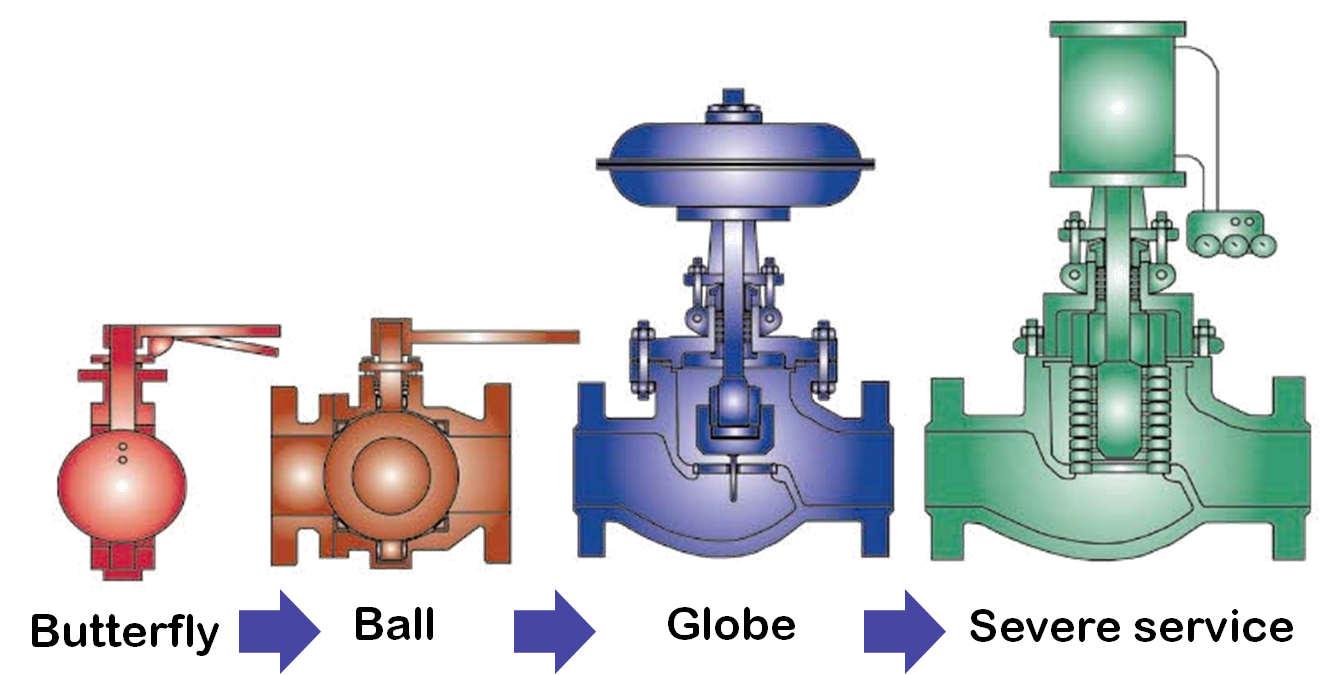
5 common types:
– Globe
– Gate
– Ball
– Butterfly
– Eccentric-Plug
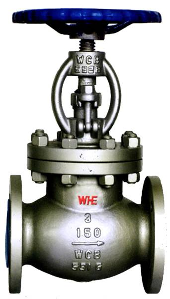
Globe valves
Globe valves are used for throttling flow.
They can be given a specific 'characteristic', relating valve opening to flow.
An actuator coupled to the valve stem would provide valve movement.
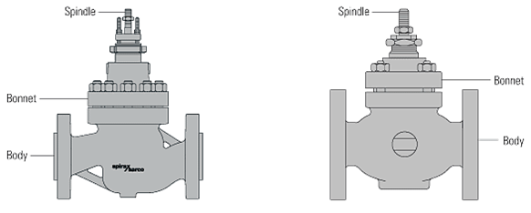
Globe Valve
A valve with a linear motion plug, one or more ports, and a body distinguished
by a globular shaped cavity around the port region.
 Globe Valve
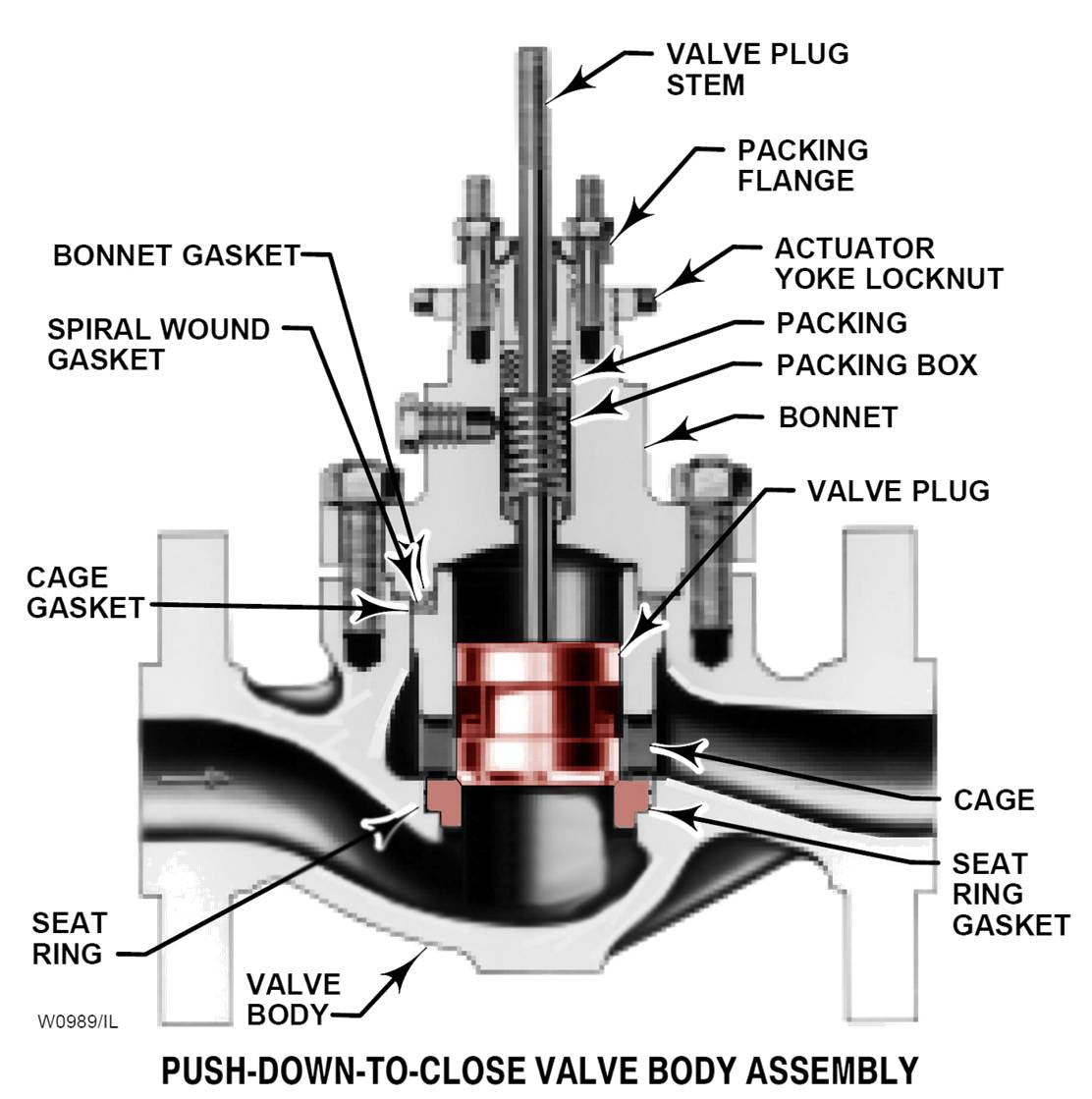
The major parts of globe valves are:
The body.
The bonnet.
The cage
The valve seat and valve plug.
The valve stem (which connects to the actuator).
The sealing arrangement between the valve stem and the bonnet.
Bonnet:
The portion of the valve that contains the packing box and stem seal
and guides the stem. It provides the principal opening to the body cavity
for assembly of internal parts or it can be an integral part of the valve body.
It can also provide for the attachment of the actuator to the valve body.
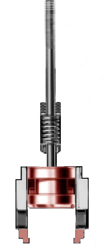
Trim
The internal components of a valve that
modulate the flow of the controlled fluid. In a
globe valve body, trim would typically include
the plug, seat ring, cage, stem, and stem pin.
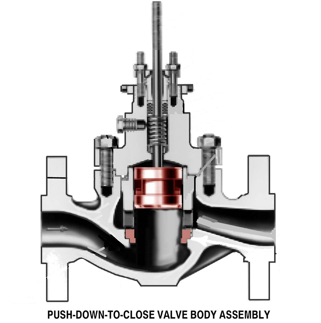
Cage
A part of a valve trim that surrounds the plug and can provide flow
characterization and/or a seating surface. It also provides stability, guiding,
balance, and alignment, and facilitates assembly of other parts of the valve trim.
The walls of the cage contain openings that usually determine the flow
characteristic of the control valve.
Plug
The part of the valve that is positioned in the flow path to modify
the rate of flow through the valve.
Seat Ring
A part of the valve body assembly that provides a seating surface for
the plug and can provide part of the flow control orifice.
Valve Stem
In a linear motion valve, the part that connects the actuator stem with the plug.
Yoke
The structure that rigidly connects the actuator power unit to the valve.
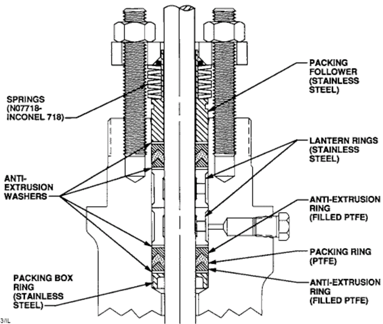
Packing Box (Assembly)
The part of the bonnet assembly used to seal against leakage around the plug stem.
Included in the packing box assembly are various combinations of some or all of the
following component parts: packing, packing follower, packing nut, lantern ring, packing
spring, packing flange, packing flange studs or bolts, packing flange nuts, packing ring,
packing wiper ring, felt wiper ring, belleville springs, anti-extrusion ring.
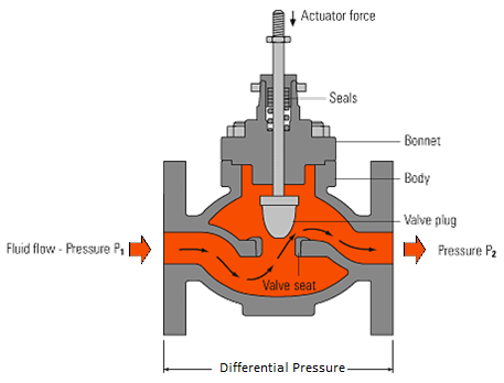
Single seat two-port globe valve.
The fluid flow is pushing against the valve plug and tends to keep the plug
off the valve seat. The difference in pressure upstream (P1) and downstream
(P2) of the valve, against which the valve must close, is known as the
differential pressure (DP). The maximum differential pressure against which a valve
can close will depend upon the size and type of valve and the actuator operating it.
Two-port Valve
If a large valve, having a large orifice, is used to pass greater flows, then the force that the actuator must develop in to close the valve will also increase. For large flows through the valve, or when very high differential pressures exist,
the point will be reached where it becomes impractical to provide sufficient force to close a conventional single seat valve.
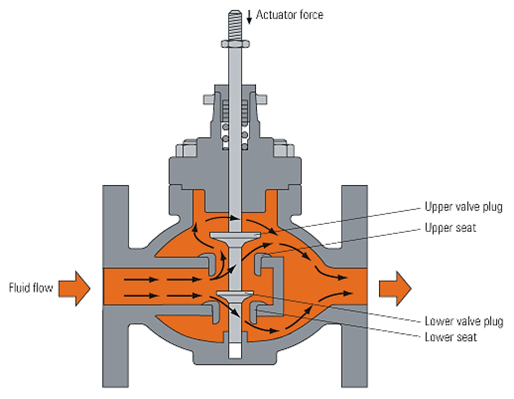
The solution to this problem is the double seat two-port valve.
The double seat valve has two valve plugs on a common spindle, with two valve seats. The valve seats be kept smaller (since there are two of them) since the forces are partially balanced.
This means that although the differential pressure is trying to keep the top valve plug off its seat (as with a single seat valve) it is also trying to push down and close the lower valve plug.
However, a potential problem exists with any double seat valve.
Because of manufacturing tolerances and differing coefficients of expansion,
few double seat valves can be guaranteed to give good shutoff tightness.
Shut-off tightness
Control valve leakage is classified with respect to how much the valve will leak when fully closed.
The leakage rate across a standard double seat valve is at best Class III, (a leakage of 0.1% of full flow) which may be too much to make it suitable for certain applications.
Consequently, because the flow paths through the two-ports are different, the forces may not remain in balance when the valve opens.
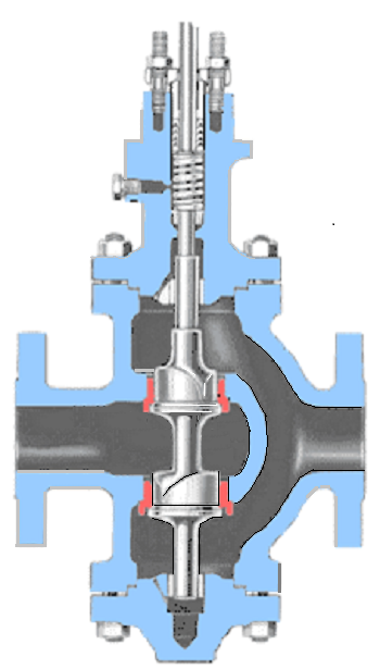
Reverse Double-Ported Globe-Style Valve Body
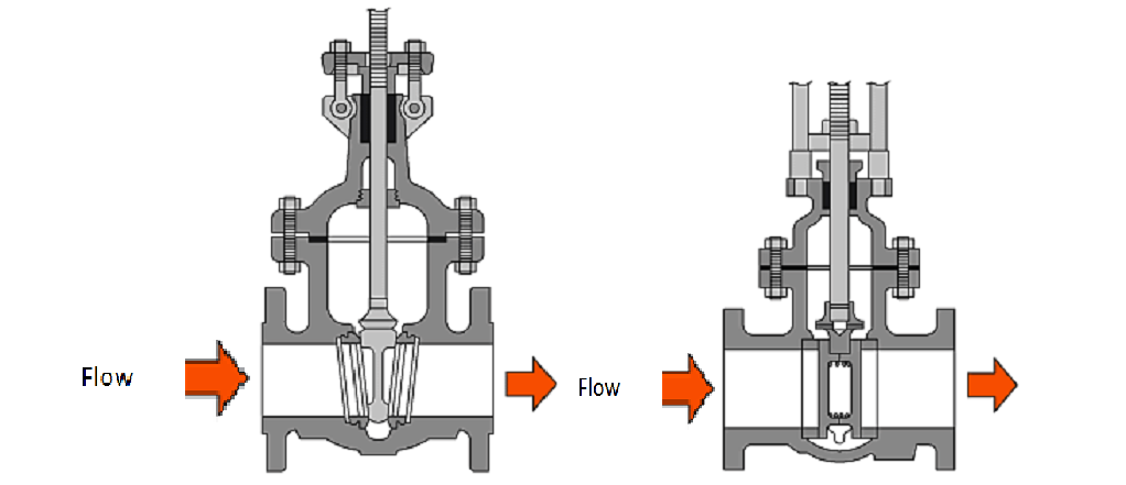
Slide Valves
Slide valves tend to come in two different designs; wedge gate type
and parallel slide type. Both types are well suited for isolating fluid flow,
as they give a tight shut-off and, when open, the pressure drop across them is very small.
Both types are used as manually operated valves, but if automatic actuation is required,
the parallel slide valve is usually chosen, whether for isolation or control.
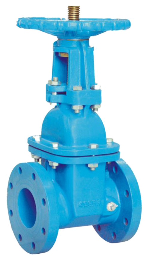
Gate Valve
Rotary type valves, often called quarter-turn valves, include plug valves
ball valves and butterfly valves. All require a rotary motion to open and
close, and can easily be fitted with actuators.
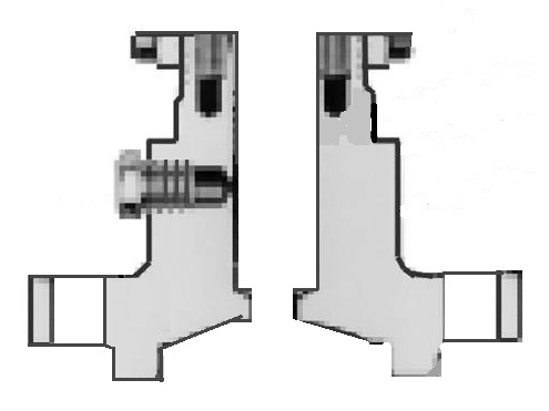
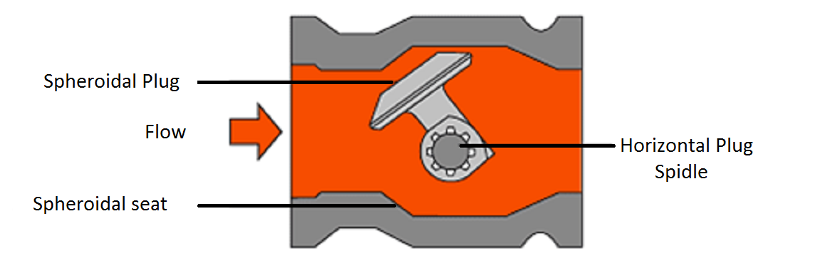
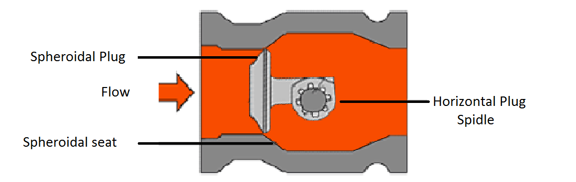
Eccentric Plug or Camflex Valve
Path of eccentric plug minimizes contact with the seat ring when opening,
reducing seat wear and friction, prolonging seat life, and improving throttling performance.
Self-centering seat ring and rugged plug allow forward or
reverse flow with tight shutoff in either direction.
Plug, seat ring and retainer are available in hardened materials,
including ceramics, for selection of erosion resistance.
Sectional of Eccentric-Plug Control Valve Body
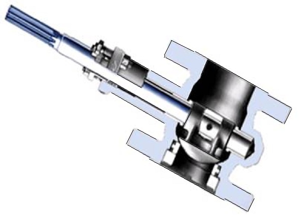
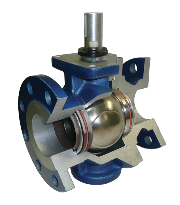
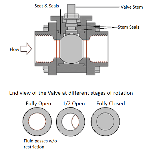
Ball valves
A ball valve consists of a spherical ball located between two sealing rings
in a simple body form. The ball has a hole allowing fluid to pass through.
When aligned with the pipe ends, this gives either full bore or nearly
full bore flow with very little pressure drop.
Rotating the ball through 90° opens and closes the flow passage.
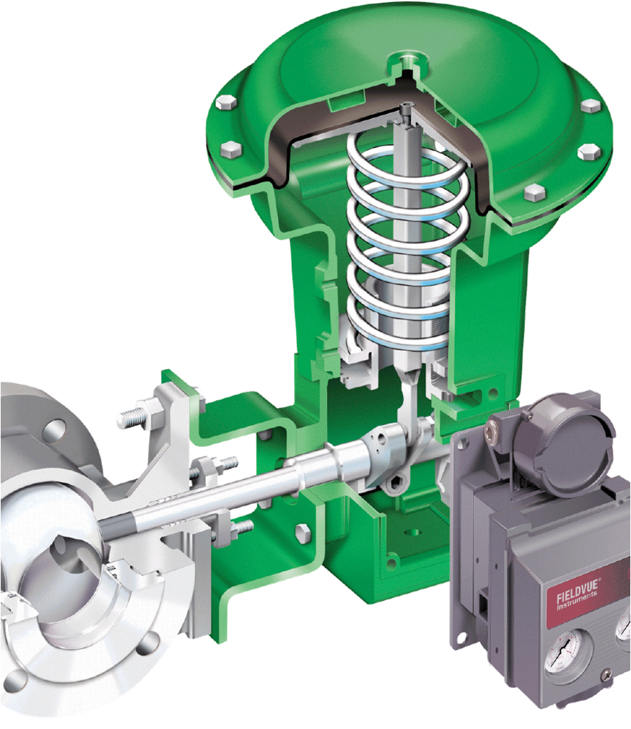
Ball valves designed specifically for control purposes will have
characterized balls or seats, to give a predictable flow pattern.
Ball Valve with Pneumatic Actuator
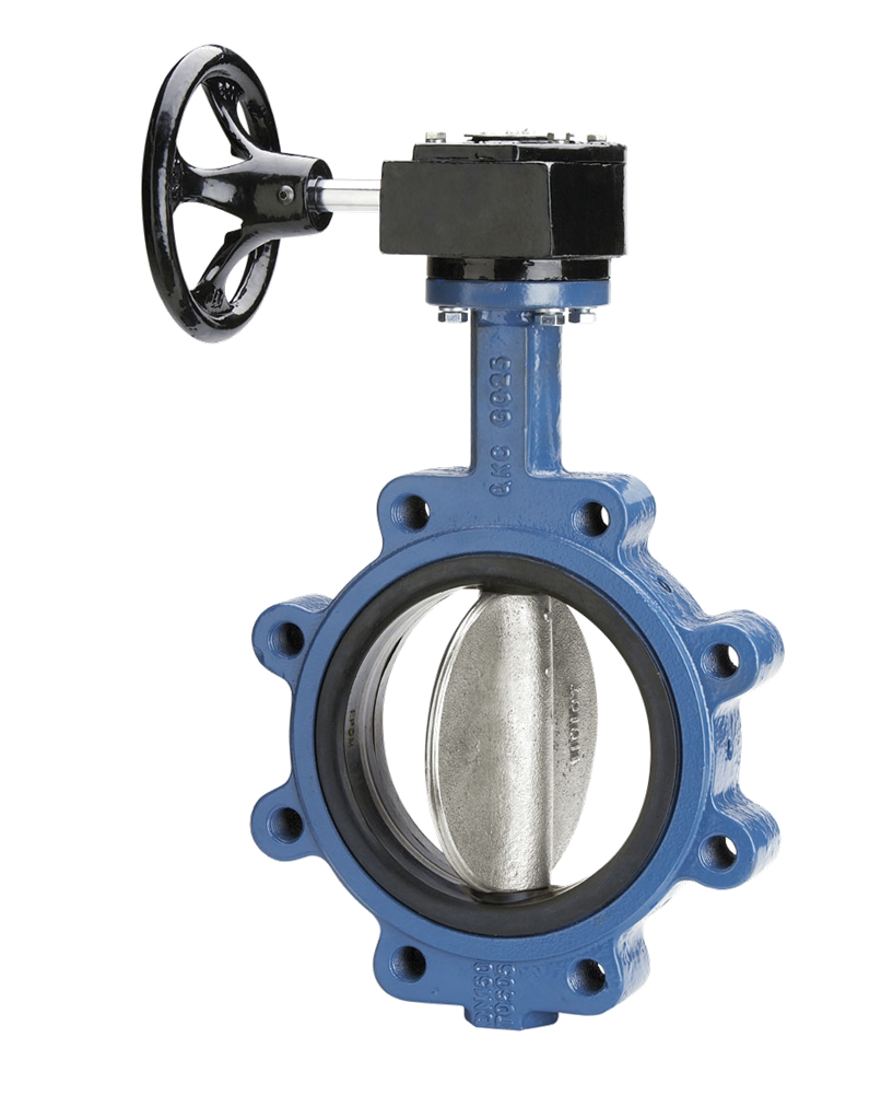
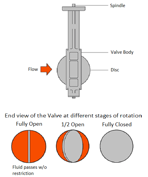
Butterfly Valve
A butterfly valve, consists of a disc rotating in trunnion bearings.
In the open position the disc is parallel to the pipe wall,
allowing full flow through the valve.
In the closed position it is rotated against a seat.
Butterfly Valve
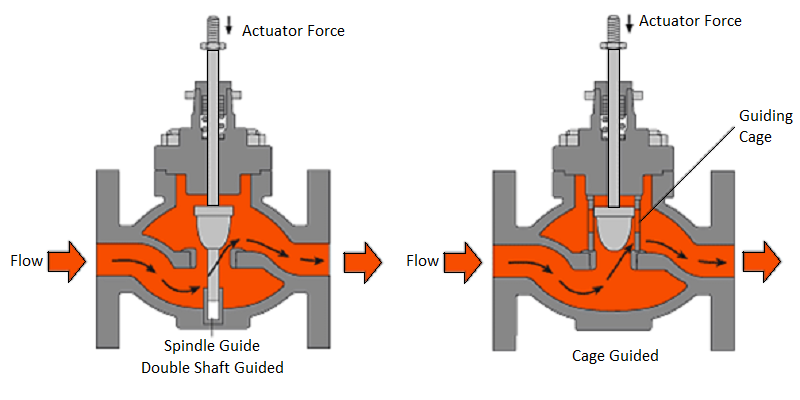
Ways of Guiding the Valve Plug
Valves also have different ways of guiding the valve plug inside the body.
One common guidance method, is the 'double guided' method,
where the spindle is guided at both the top and the bottom of its length.
Another type is the 'guided plug' method where
the plug may be guided by a cage or a frame.
Some valves can employ perforated plugs,
which combine plug guidance and noise reduction
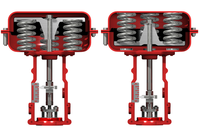
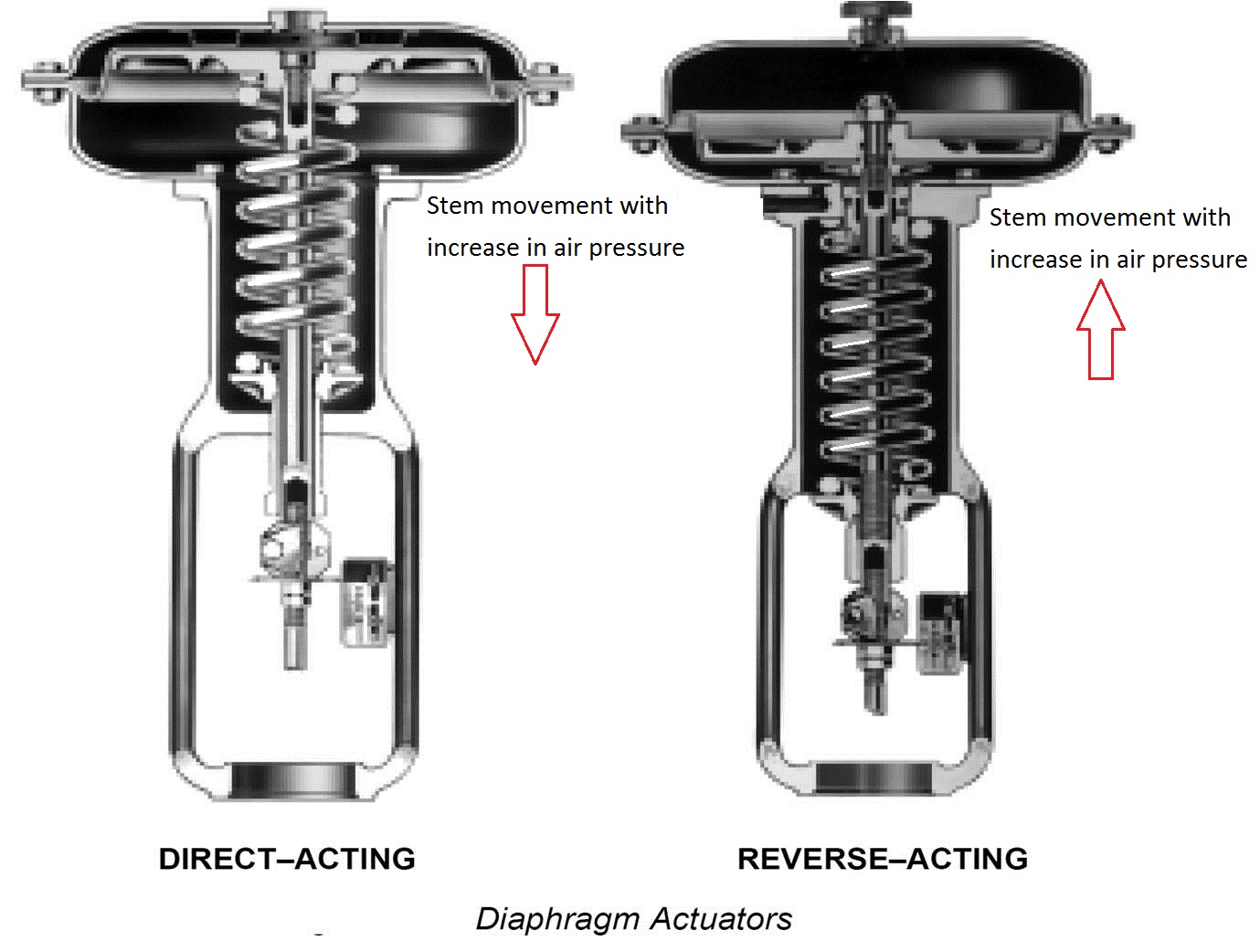
Direct Acting Reverse Acting
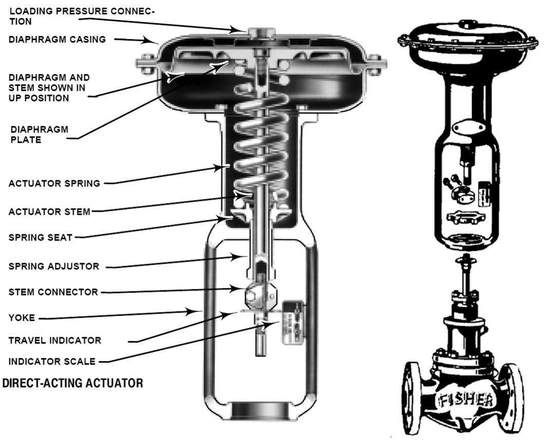
Diaphragm Actuators
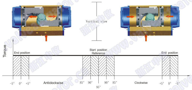
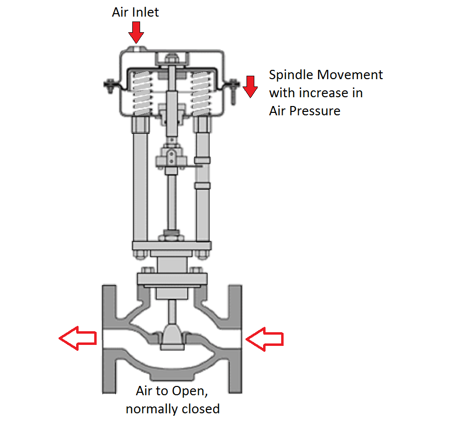
Pneumatic actuators
Pneumatic actuators are commonly used to actuate control valves and are
available in two main forms; piston actuators and diaphragm actuators.
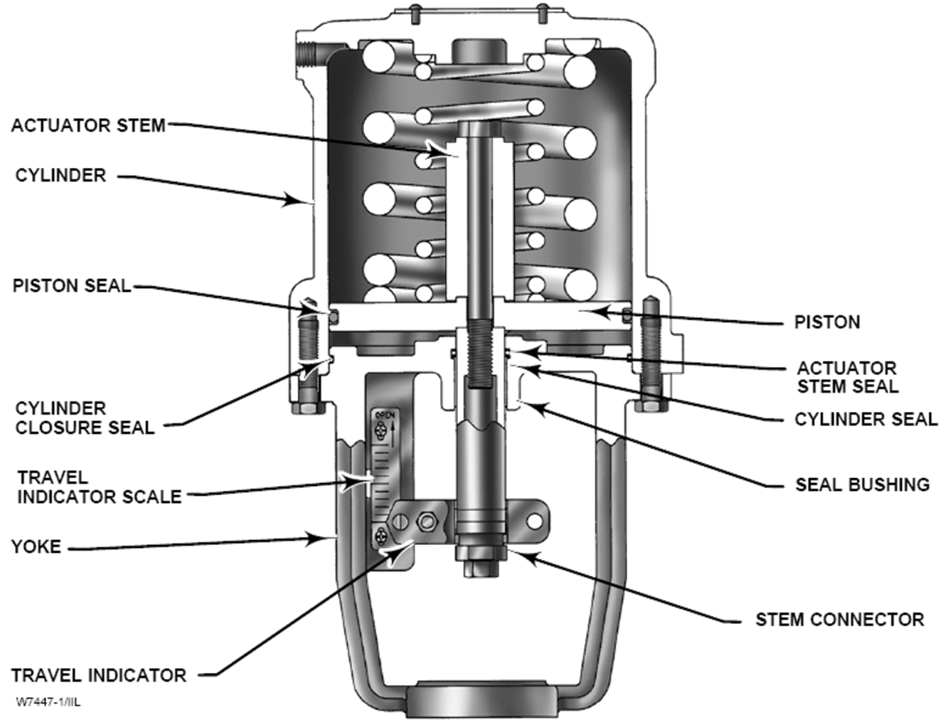
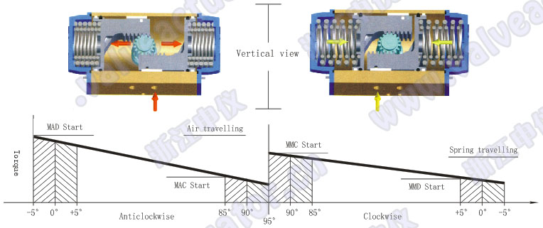
Double-Acting Piston Actuator with Bias Spring Piston actuators are used where the stroke of a diaphragm actuator
would be too short or the thrust is too small.
The compressed air is applied to a solid piston contained within a solid cylinder.
Piston actuators can be single acting or double acting, can withstand higher
input pressures and can offer smaller cylinder volumes, which can act at high speed.
Diaphragm actuators have compressed air applied to a flexible membrane
called the diaphragm. A rolling diaphragm is where the effective
diaphragm area is virtually constant throughout the actuator stroke.
These types of actuators are single acting, in that air is only supplied to
one side of the diaphragm, and they can be either direct acting
(spring-to-retract) or reverse acting (spring-to-extend).
Direct acting actuator (spring-to-retract)
With increasing air pressure, stem movement is the opposite the reverse acting actuator.
A direct acting pneumatic actuator is coupled to a control valve with a reverse acting plug
(sometimes called a 'hanging plug').
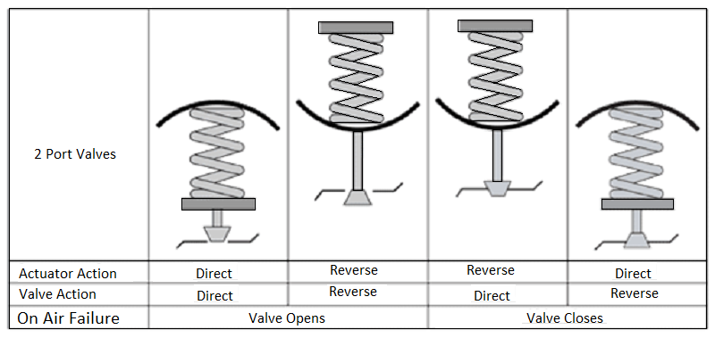
The choice between direct acting and reverse acting actuators depends on what
position the valve should be in the event of failure of the air supply.
Should the valve close or be wide-open?
This choice depends upon the nature of the application and safety.
The combination of actuator and valve type must be considered.
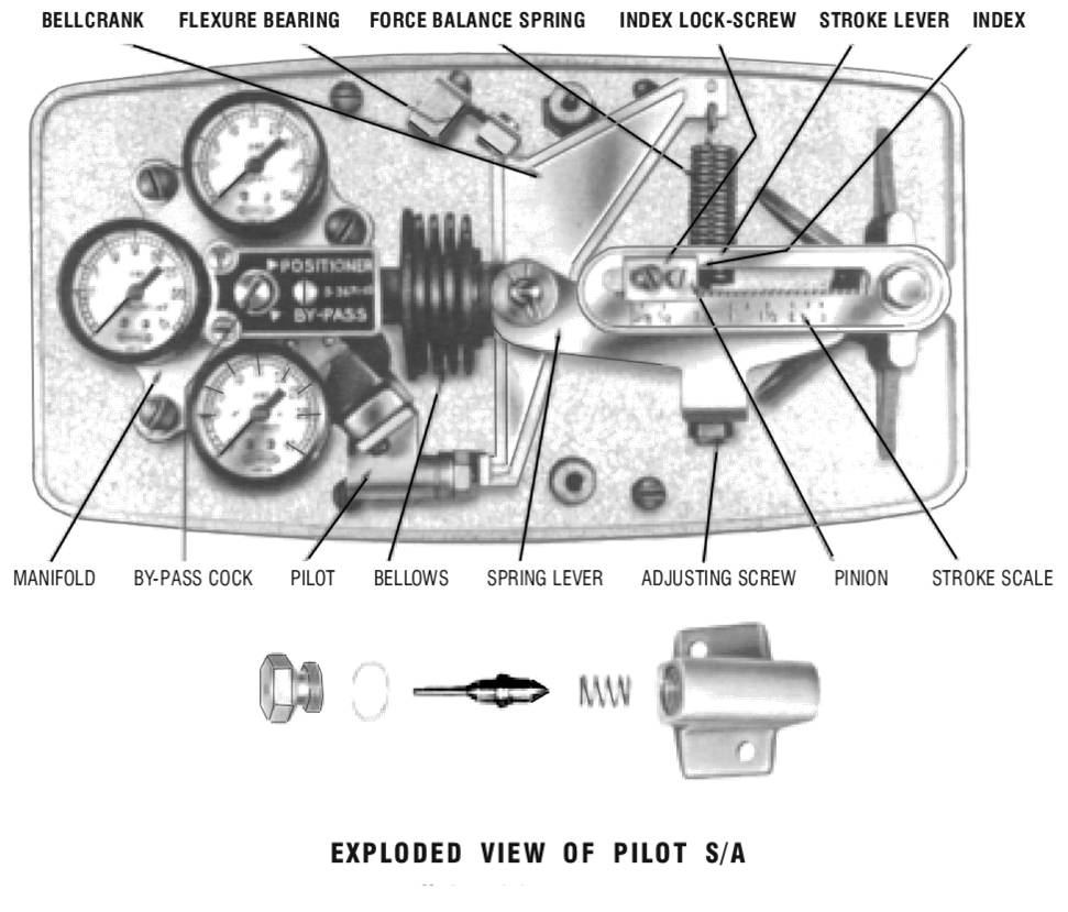
Positioners
For many applications, the 0.2 to 1 bar pressure in the diaphragm chamber
may not be enough to cope with friction and high differential pressures.
A higher control pressure and stronger springs could be used,
but the practical solution is to use a positioner.
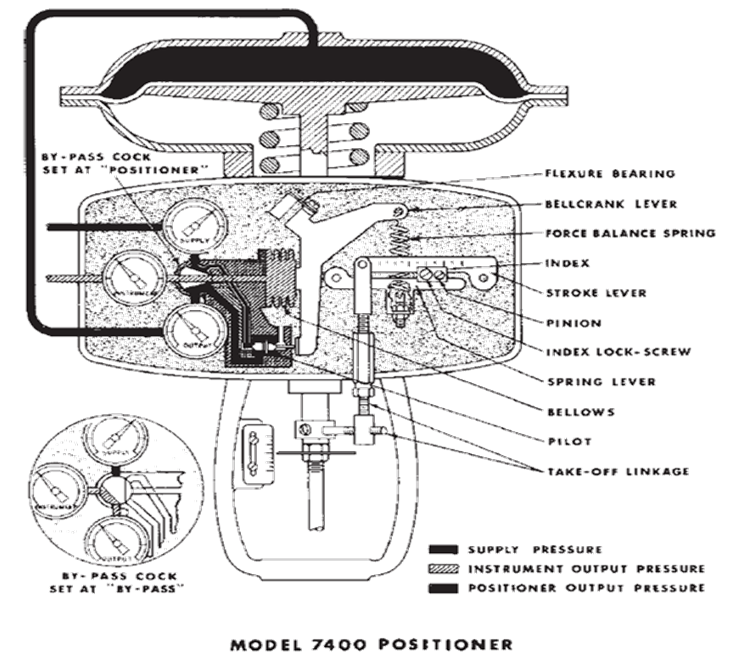
This is usually fitted to the yoke or pillars of the actuator,and it is linked to the spindle of the actuator by a feedback arm in order to monitor the valve position.
It has its own higher-pressure air supply, used to position the valve.
Think of the valve positioner as a controller with the input signal as the setpoint (SV) and the valve position as the process value (PV), and the pressure to the actuator is the manipulated variable MV). The positioner will vary the actuator pressure until the input signal and valve position are equal.
When a positioner is fitted to an 'air-to-open' valve and actuator arrangement,
the spring range may be increased to increase the closing force,
and hence increase the maximum differential pressure a particular valve can tolerate.
The air pressure will also be adjusted as required to overcome friction, thereby reducing hysteresis effects
Summary -Positioners
A positioner ensures that there is a linear relationship between the signal input pressure from the control system and the position of the control valve.
This means that for a given input signal, the valve will always attempt to maintain
the same position regardless of changes in valve differential pressure,
stem friction, diaphragm hysteresis and so on.
A positioner may be used as a signal amplifier or booster.
It accepts a low pressure air control signal and, by using its own higher pressure input, multiplies this to provide a higher pressure output air signal to the actuator diaphragm,
if required, to ensure that the valve reaches the desired position.
To ensure that the full valve differential pressure can be accepted,
it is important to adjust the positioner zero setting so that no
air pressure opposes the spring force when the valve is seating.
When to use a positioner:
A) When accurate valve positioning is required.
B) To speed up the valve response.
The positioner uses higher pressure to adjust the valve position.
C) To increase the pressure that a particular actuator and valve can close against.
D) Overcome friction in the valve (packing)
E) To linearise a non-linear actuator.
F) Where varying differential pressures within the fluid would cause the plug position to vary.
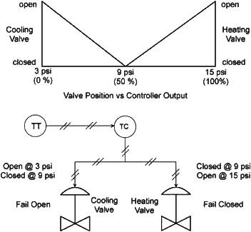
G) To split the range of a controller.
A split range configuration ensures that only one valve is open at any time.
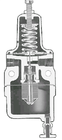
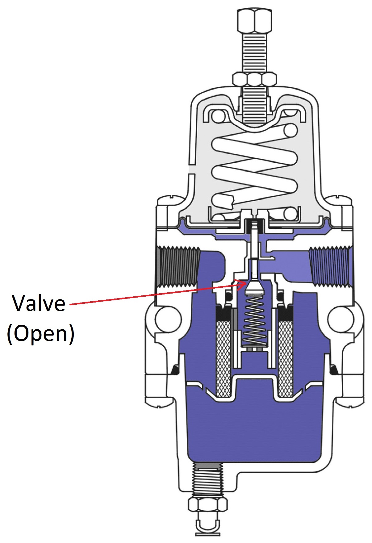
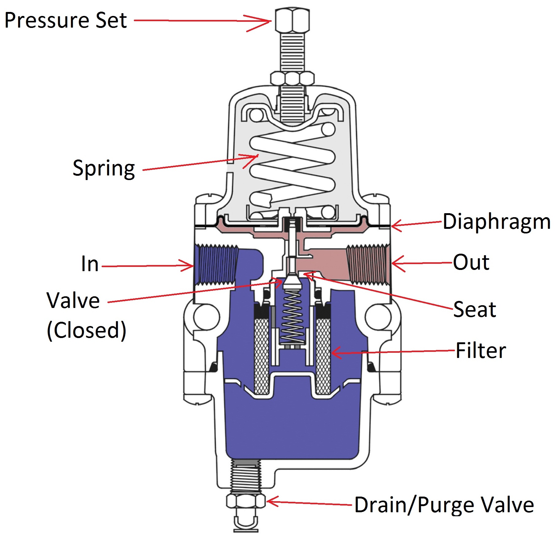
Pressure Regulator
A pressure regulator keeps the outlet pressure constant at the set value.
The pressure is set by turning the Pressure Set screw. Turning it clockwise increases tension on the spring, which pushes the diaphragm and opens the valve. The outlet pressure rises pushing back the diaphragm until it balances the spring tension. The balancing pressure is the regulator set value.
Valve Sizing and Selection
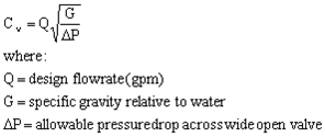
What is Cv?
The definition of Cv factor is the number of G.P.M. that will pass through a valve with a
pressure drop of one (1) psi. A unit of measure for comparing valve flows.
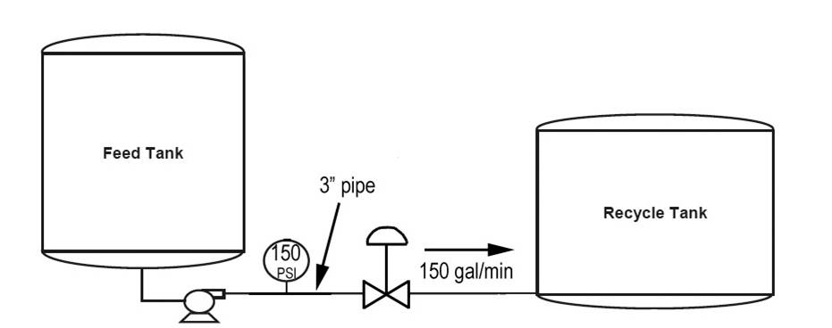
STEP #1: Define the system
The system is pumping water from one tank to another through a piping system with a total
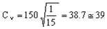
pressure drop of 150 psi. The fluid is water at 70 0F. Design (maximum) flowrate of 150 gpm, operating flowrate of 110 gpm, and a minimum flowrate of 25 gpm. The pipe diameter is 3 inches. At 70 0F, water has a specific gravity of 1.0.
STEP #2: Define a maximum allowable pressure drop for the valve
When defining the allowable pressure drop across the valve, you should first investigate the pump. Remember that the system pressure drop is limited by the pump.
The usual rule of thumb is that a valve should be designed to use 10-15% of the total pressure drop or 10 psi, whichever is greater. For our system, 10% of the total pressure drop is 15 psi which is what we'll use as our allowable pressure drop when the valve is wide open (the pump in our system is easily capable of the
additional pressure drop).
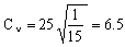
STEP #3: Calculate the valve characteristic
STEP #4: Preliminary valve selection
Don't make the mistake of trying to match a valve with your calculated Cv value. The Cv value should be used as a guide in the valve selection, not a hard and fast rule. Some other considerations are:
a. Never use a valve that is less than half the pipe size
b. Avoid using the lower 10% and upper 20% of the valve stroke. The valve is much easier to control in the 10-80% stroke range.
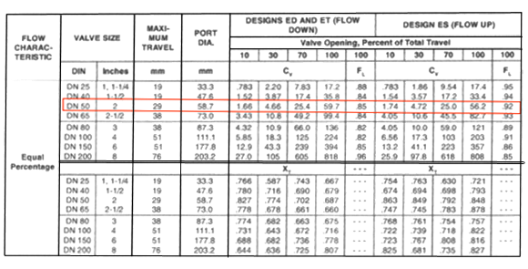
Before a valve can be selected, you have to decide what type of valve will be used. For our case, we'll assume we're using an equal percentage globe valve. The valve chart for this type of valve is shown below.
For our case, it appears the 2 inch valve will work well for our Cv value at about 80-85% of the stroke range. Notice that we're not trying to squeeze our Cv into the 1 1/2 valve which would need to be at 100% stroke to handle our
maximum flow. If this valve were used, two consequences would be experienced: the pressure drop would be a little higher than 15 psi at our design (max) flow and the valve would be difficult to control at maximum flow. Also, there would be no room for error with this valve, but the valve we've chosen will allow for flow surges beyond the 150 gpm.
STEP #5: Check the Cv and stroke percentage at the minimum flow
If the stroke percentage falls below 10% at our minimum flow, a smaller valve may have to be used in some cases. Judgement plays role in
many cases. For example, is your system more likely to operate closer to the maximum
flowrates more often than the minimum flowrates? Or is it more likely to operate near
the minimum flowrate for extended periods of time. It's difficult to find the perfect valve, but you should find one rates well most of the time.
Referring back to our valve chart, we see that a Cv of 6.5 would correspond to a stroke
percentage of around 35-40% which is certainly acceptable.
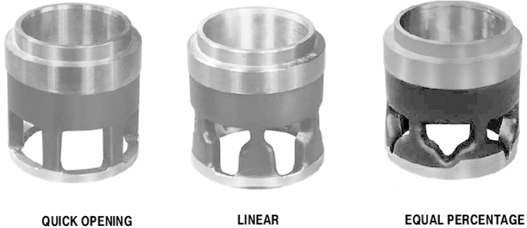
SELECTING A VALVE TYPE
When speaking of valves, it's easy to get lost in the terminology. Valve types are used to describe the mechanical characteristics and geometry (Ex/ gate, ball, globe valves). We'll use valve control to refer to how the valve travel or stroke (openness) relates to the flow:
1. Equal Percentage: equal increments of valve travel produce an equal percentage in flow change
2. Linear: valve travel is directly proportional to the valve stoke
3. Quick opening: large increase in flow with a small change in valve stroke
So how do you decide which valve control to use? Here are some rules of thumb for each one:
1. Equal Percentage (most commonly used valve control)
a. Used in processes where large changes in pressure drop are expected
b. Used in processes where a small percentage of the total pressure drop is
permitted by the valve
c. Used in temperature and pressure control loops
2. Linear
a. Used in liquid level or flow loops
b. Used in systems where the pressure drop across the valve is expected to remain fairly constant (ie. steady state systems)
3. Quick Opening
a. Used for frequent on-off service
b. Used for processes where "instantly" large flow is needed (ie. safety systems or cooling water systems)
Gate Valves
Best Suited Control: Quick Opening
Recommended Uses:
1. Fully open/closed, non-throttling
2. Infrequent operation
3. Minimal fluid trapping in line
Applications: Oil, gas, air, slurries, heavy liquids, steam, noncondensing gases, and corrosive liquids
Advantages: Disadvantages:
1. High capacity 1. Poor control
2. Tight shutoff 2. Cavitate at low
3. Low cost pressure drops 3. Cannot be used for throttling
4. Little resistance to flow
Globe Valves
Best Suited Control: Linear and Equal percentage
Recommended Uses:
1. Throttling service/flow regulation
2. Frequent operation
Applications: Liquids, vapors, gases, corrosive substances, slurries
Advantages: Disadvantages:
1. Efficient throttling 1. High pressure drop
2. Accurate flow control 2. More expensive
3. Available in multiple ports
Ball Valves
Best Suited Control:Quick opening, linear
Recommended Uses:
1. Fully open/closed, limited-throttling
2. Higher temperature fluids
Applications:Most liquids, high temperatures, slurries
Advantages: Disadvantages:
1. Low cost 1. Poor throttling characteristics
2. High capacity 2. Prone to cavitation
3. Low leakage and maint.
4. Tight sealing with low torque
Butterfly Valves
BestSuitedControl: Linear, Equal percentage
Recommended Uses:
1. Fully open/closed or throttling services
2. Frequent operation
3. Minimal fluid trapping in line
Applications: Liquids, gases, slurries, liquids with suspended solids
Advantages: Disadvantages:
1. Low cost and maint. 1. High torque required
2. High capacity for control 2. Prone to cavitation
3. Good flow control
4. Low pressure drop at lower flows
Other Valves
Another type of valve commonly used in conjunction with other valves is called a check valve. Check valves are designed to restrict the flow to one direction. If the flow reverses direction, the check valve closes. Relief valves are used to regulate the operating pressure of incompressible flow. Safety valves are used to release excess pressure in gases or compressible fluids.
Installation and Maintenance
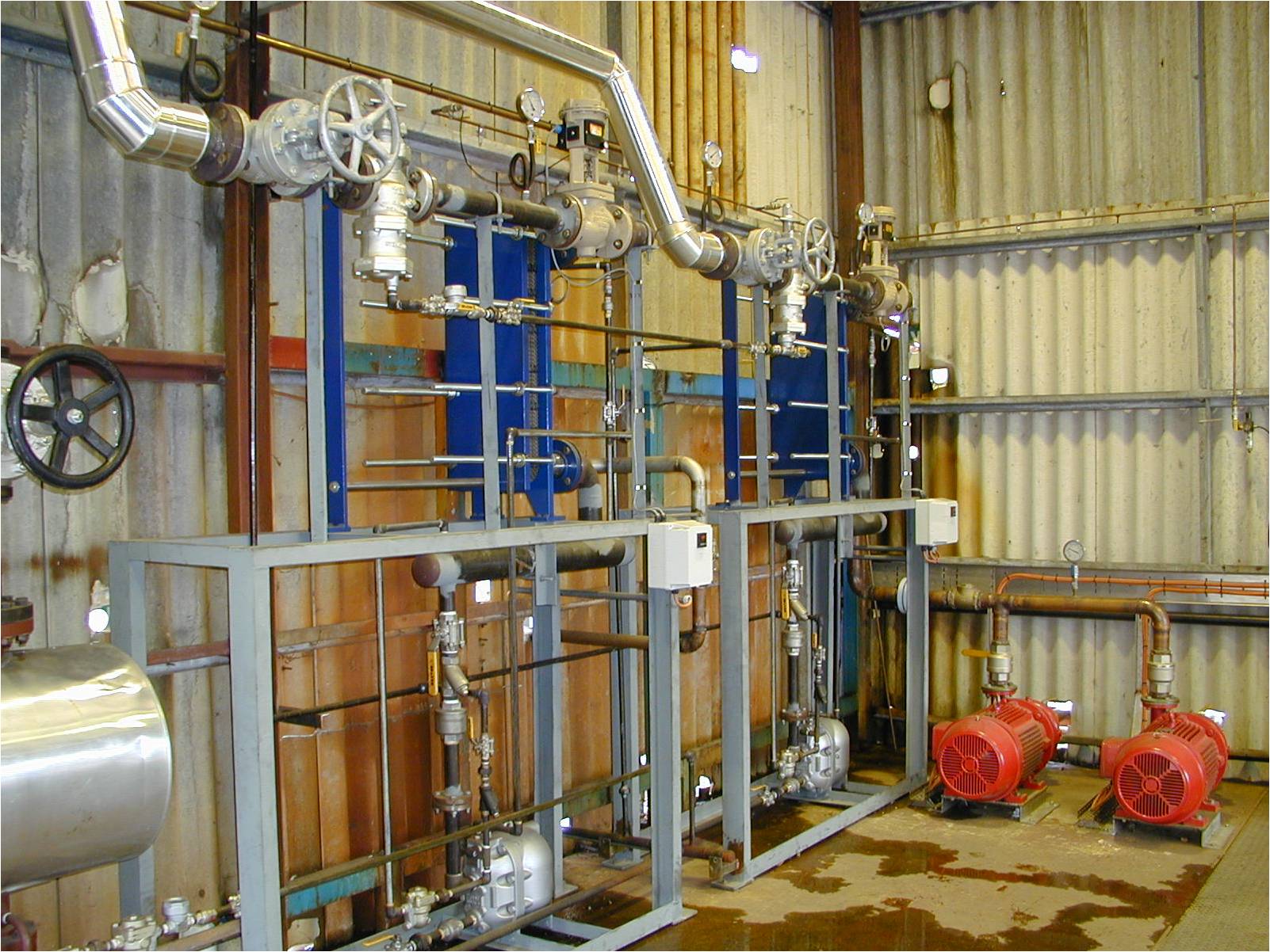
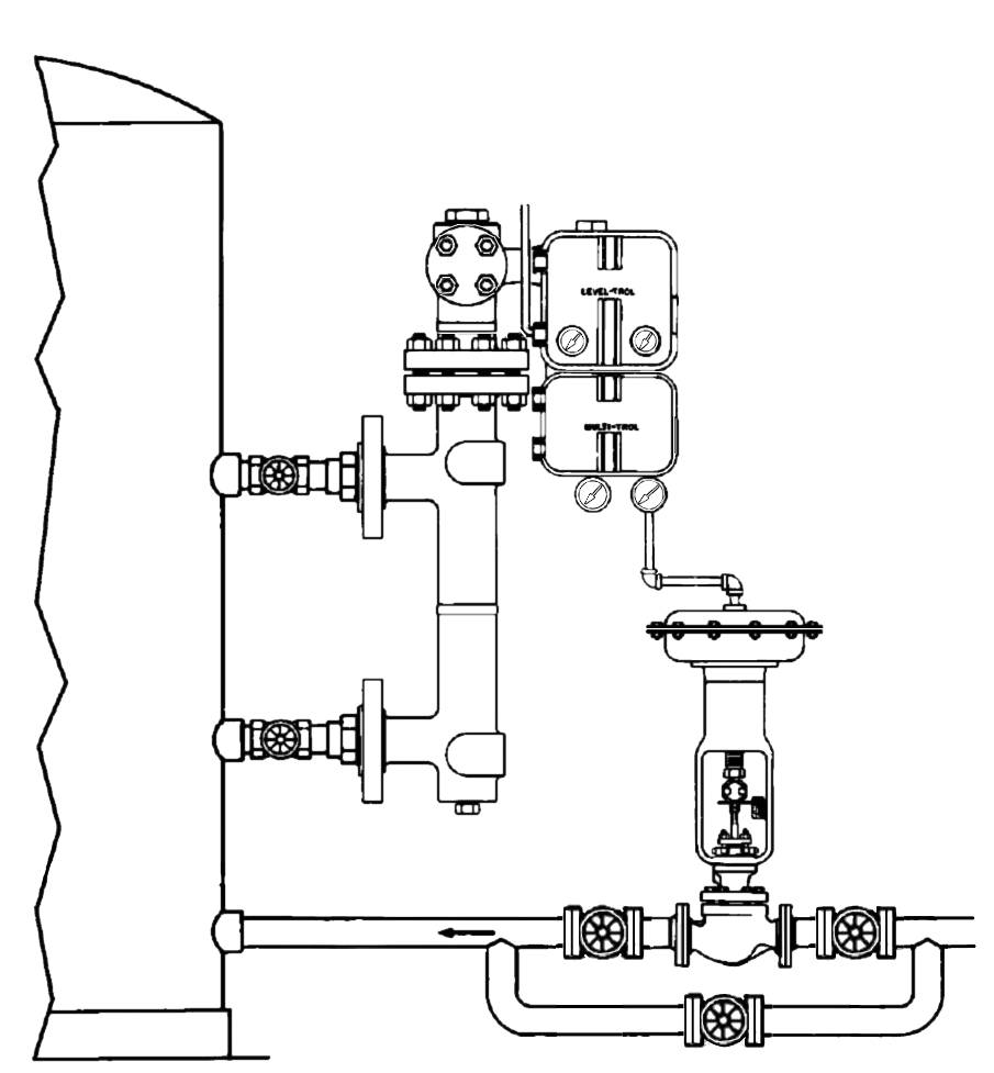
Typical Installation
Optimizing control valve efficiency depends on:
1. Correct control valve selection for the application,
2. Proper storage and protection,
3. Proper installation techniques, and
4. An effective predictive maintenance program.
Be Sure the Pipeline Is Clean
Foreign material in the pipeline could damage the seating surface of the valve or obstruct the movement of the valve plug, ball, or disk so that the valve does not shut off properly.
1 Clean all pipelines before installing.
2 Make sure pipe scale, metal chips, welding slag, and other foreign materials are removed.
3 Inspect pipe flanges to ensure a smooth gasket surface.
Inspect the Control Valve
Although valve manufacturers take steps to prevent shipment damage, such damage is
possible and should be discovered and reported before the valve is installed.
1 Do not install a control valve known to have been damaged in shipment or while in storage.
2 Before installing, check for and remove all shipping stops and protective plugs or gasket surface covers.
3 Check inside the valve body to make sure no foreign objects are present.
Use Good Piping Practices
1 Most control valves can be installed in any position. However, the most common method is
with the actuator vertical and above the valve body.
2 If horizontal actuator mounting is necessary, consider additional vertical support for the actuator.
3 Be sure the body is installed so that fluid flow will be in the direction indicated by the flow arrow
4 Be sure to allow ample space above and below the valve to permit easy removal of the actuator
or valve plug for inspection and maintenance.
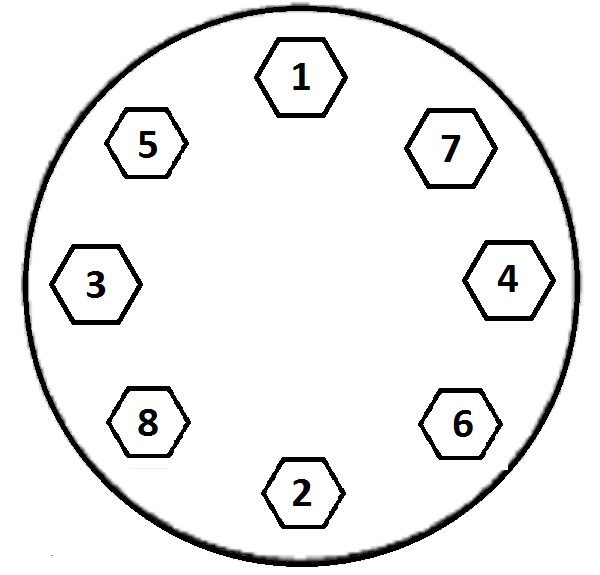
Bolt tightening sequence
5 Be sure the flanges are properly aligned to provide uniform contact of the gasket
surfaces. Snug up the bolts gently after establishing proper flange alignment.
6 Tighten bolts in a criss-cross pattern to prevent leaks and to avoid the possibility of
damaging, or even breaking, the flange.
7 Install pressure taps upstream and downstream of the control valve are for
checking flow capacity or pressure drop.
Locate such taps in straight runs of pipe away from elbows, reducers, or expanders. This location minimizes inaccuracies resulting from fluid turbulence.
8 Use1/4- or 3/8-inch (6-10 millimeters) tubing for the pressure connection on the actuator to
the controller. Keep this distance relatively short and minimize the number of fittings and
elbows to reduce system time lag. If the distance must be long, use a valve positioner
or a booster with the control valve.
Spring-and-Diaphragm Actuator
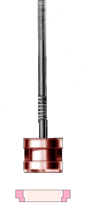
Stem Packing
Provides the pressure seal around the stem, should be replaced if leakage develops, or if
the valve is completely disassembled for other maintenance or inspection. Before loosening
packing nuts, make sure there is no pressure in the valve body.
Blow out the old packing rings by applying pressure to the lubricator hole in the bonnet.
Clean the packing box. Inspect the stem for scratches or imperfections that could damage
new packing.
Check the trim and other parts as appropriate. After re-assembling, tighten body/bonnet
bolting in a sequence similar to that for flanges. Slide new packing parts over the stem in proper
sequence, being careful that the stem threads do not damage the packing rings. Adjustpacking by
following the manufacturer’s instructions.
Valve Stem Packing Assemblies
Seat Rings
Severe service conditions can damage the seating surface of the seat ring(s) so that
the valve does not shut off satisfactorily.
Grinding or lapping the seating surfaces will improve shutoff if damage is not severe.
For severe damage, replace the seat ring.
Grinding Metal Seats
For cage-style constructions, bolt the bonnet or bottom flange to the body with the gaskets
in place to position the cage and seat ring properly and to help align the valve plug with
the seat ring while grinding.
Clean seating surfaces, and test for shutoff after grinding. Repeat if leakage is still excessive.
Seat Ring Puller
Replacing Seat Rings
Follow the manufacturer’s instructions. For threaded seat rings, use a seat ring puller.
Before trying to remove the seat ring(s), check to see if the ring has been tack-welded
to the valve body. If so, cut away the weld. On double-port bodies,
one of the seat rings is smaller than the other.
Remove all excess pipe compound after tightening the threaded seat ring.
Spot weld a threaded seat ring in place to ensure that it does not loosen.