
email: calmansys@yahoo.com
Types of Plant Documentation
Plot Plan
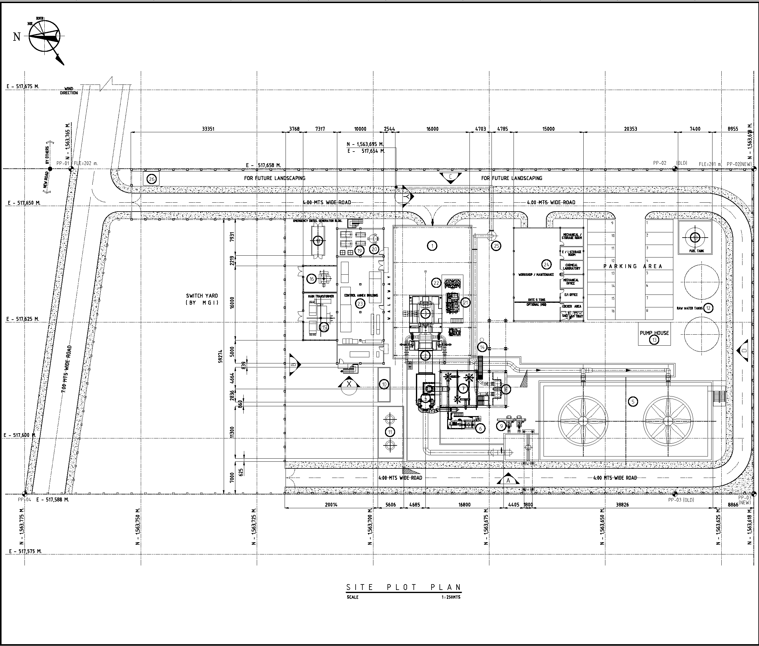
A Plot Plan shows the exact location of each equipment
Using pictorial diagrams may be informative however it is not practical, especially in a multi-loop process.
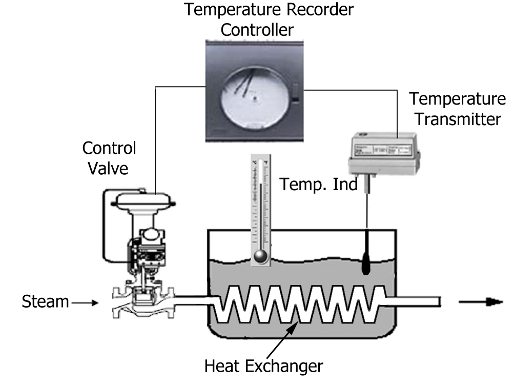
Process Pictorial Diagram
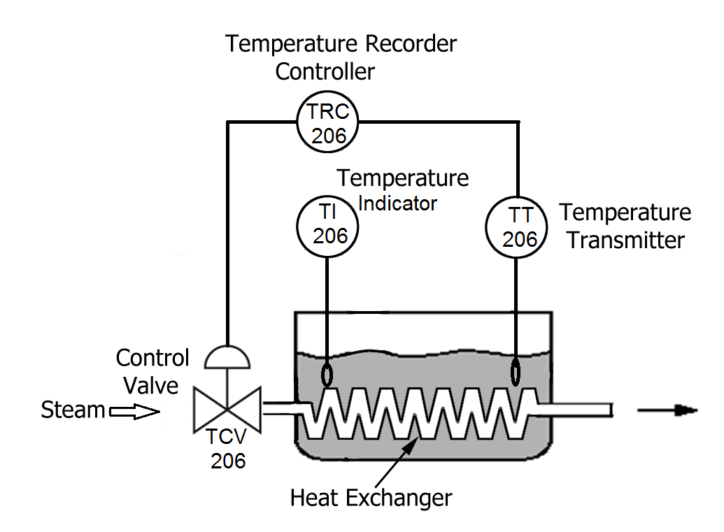
Building the P&ID
Tag Numbers
The first letter is used to designate The succeeding letter(s) designate the function of the the measured variable component or to modify the meaning of the first letter 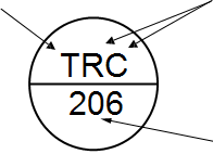 Numbers are used to designate the location of the instrument in the plant
Translating the tag TRC 206, it means the instrument is a Temperature Recording Controller, the 6th loop in Plant 200.
|
MEANINGS OF IDENTIFICATION LETTERS This table applies only to the functional identification of Instruments |
|||||
|
FIRST LETTER |
SUCCEEDING LETTERS |
||||
|
MEASURED OR INITIATING VARIABLE |
MODIFIER |
READOUT OR PASSIVE FUNCTION |
OUTPUT FUNCTION |
MODIFIER |
|
|
A |
Analysis |
Alarm |
|||
|
B |
Burner Flame |
User's choice |
User's choice |
User's choice |
|
|
C |
Conductivity (Electrical.) |
Control |
|||
|
D |
Density (Mass) or S.G. |
Differential |
|||
|
E |
Voltage (EMF) |
Primary Element |
|||
|
F |
Flow Rate |
Ratio/Fraction |
|||
|
G |
Gauging |
Glass |
|||
|
H |
Hand (Manually initiated) |
High |
|||
|
I |
Current (Electrical) |
Indicate |
|||
|
J |
Power |
Scan |
|||
|
K |
Time or Schedule |
Control Station |
|||
|
L |
Level |
Light (Pilot) |
Low |
||
|
M |
Moisture or Humidity |
Middle or Intermediate |
|||
|
N |
User's choice |
User's choice |
User's choice |
User's choice |
|
|
O |
User's choice |
Orifice/Restriction |
|||
|
P |
Pressure or Vacuum |
Point (Test connection) |
|||
|
Q |
Quantity or event |
Integrate or Totalize |
|||
|
R |
Radioactivity |
Record or Print |
|||
|
S |
Speed or Frequency |
Safety |
Switch |
||
|
T |
Temperature |
Transmit |
|||
|
U |
Multivariable |
Multifunction |
Multifunction |
Multifunction |
|
|
V |
Viscosity |
Valve, Damper or Louver |
|||
|
W |
Weight or Force |
Well |
|||
|
X |
Unclassified |
Unclassified |
Unclassified |
Unclassified |
|
|
Y |
User's choice |
Relay or Compute |
|||
|
Z |
Position |
Drive, Actuate or unclassified final control element |
|||
Instrument Location
The presence or absence of a line determines the location of the physical device. For example no line means the instrument is installed in the field near the process.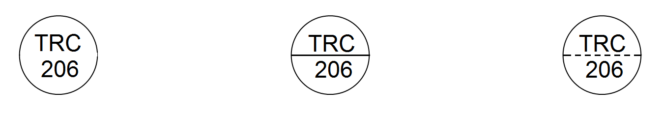
No Line Solid Line Dashed Line
The instrument is mounted The instrument is mounted The instrument is mounted out of sight in the control room in the panel (not accessible to the operator) (accessible to the operator) (not accessible to the operator)
Shared Displays/Shared Control
Some instruments are part of a Distributed Control System (DCS) where a specific controller or indicator can be selected from many others but shown in one location (like a terminal screen)
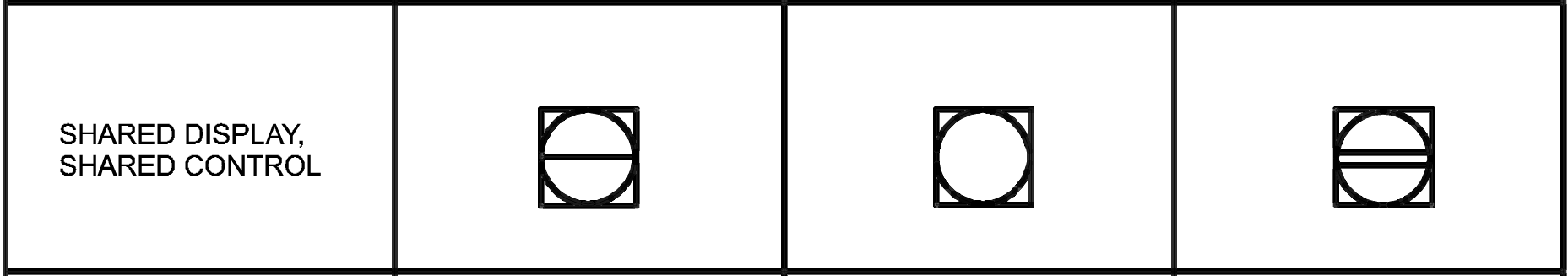
In the control room In the plant Not accessible
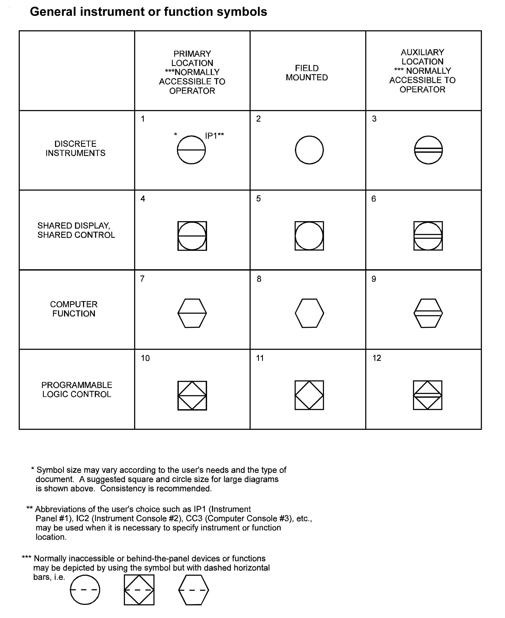
Summary of instrument type & location
Piping and Connection Symbols
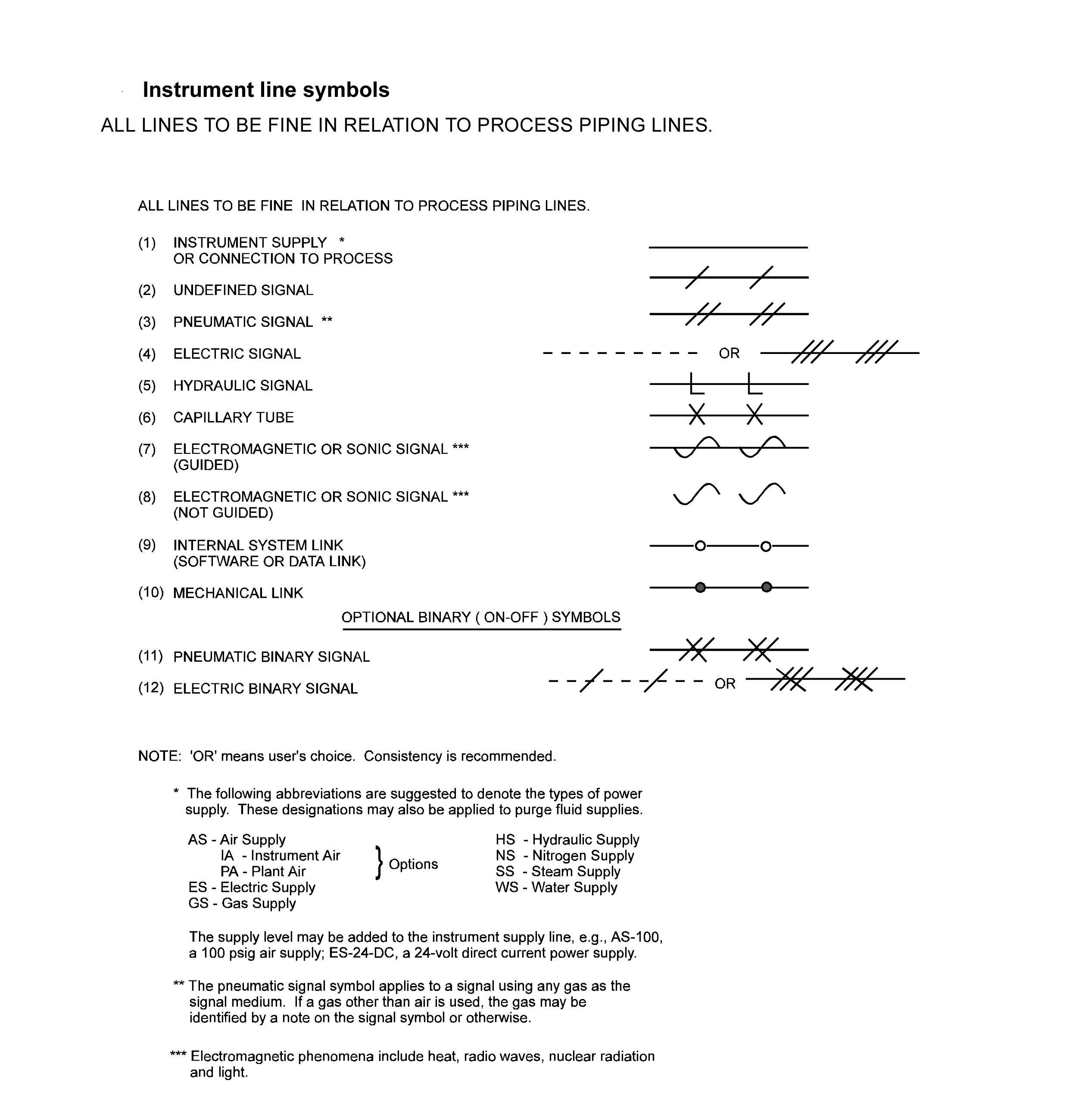
These symbols are used to identify how the instruments in the process connect to each other, and the type of signal. (electrical, pneumatic, data, etc)
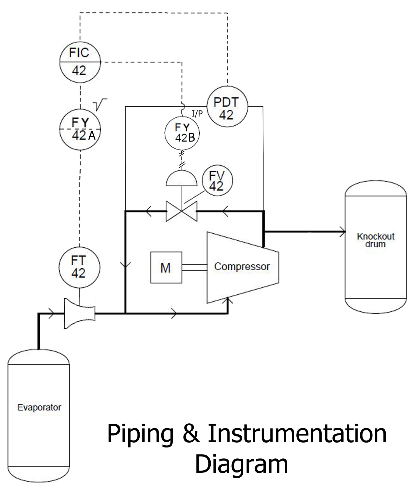
Compressor surge control P&ID
The P&ID shows how the instrument is installed in the process plant. The electrical wiring detail is shown with a Loop Drawing.
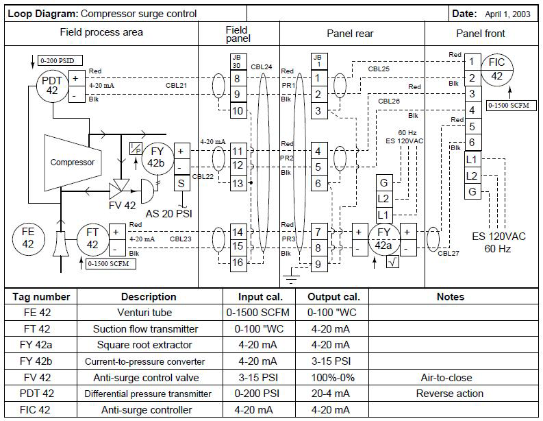
The P&ID above transformed into a Loop Sheet or Loop Drawing
Loop Drawing Details:
1. A brief description of the function of each instrument 2. Range and Calibration of Input and Output signals 3. The direction or action of the output 4. Details of each cable termination, identification tags and color 5. Junction box and Terminal block number 6. On/Off or isolation switches
A Loop Drawing shows the electrical wiring details of Instruments
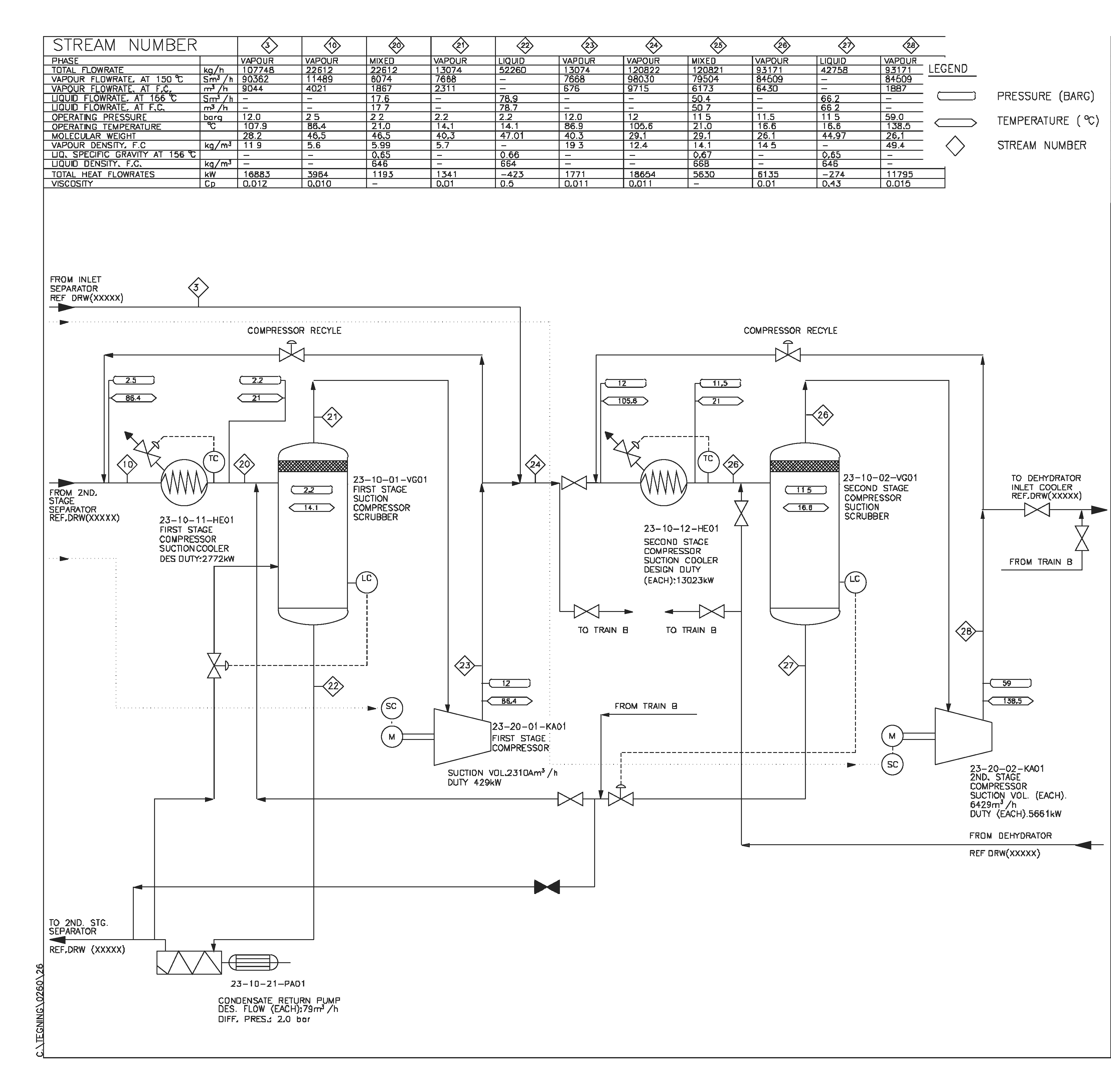
A PFD shows less detail than a P&ID and is used only to understand how the process works. It also shows the process operating conditions of major equipment. PFDs are useful for troubleshooting process problems.
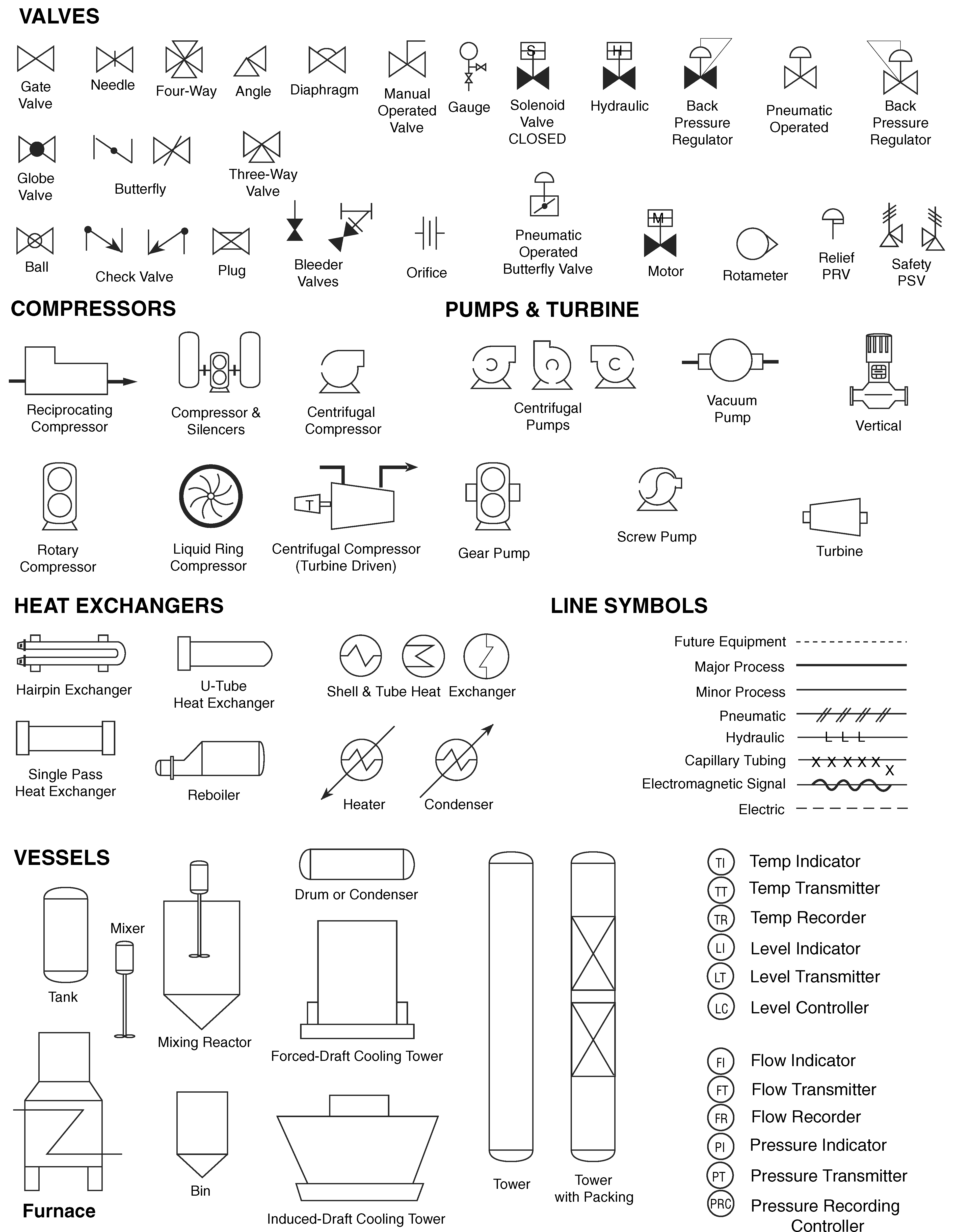
Process Equipment and Instrument Symbols
email: calmansys@yahoo.com