
What is Level?

The LEVEL of a liquid is the position of the surface of the liquid above or
below a fixed reference point, or datum line.
What is Datum Line?
The Datum Line is the zero point to which a measurement is referenced.
A zero point in level measurement is simply a starting point for making a
measurement. However, it does not necessarily mean that there is no
liquid in the tank or vessel.
Methods of Level Measurement:
1. INNAGE
2. OUTAGE OR ULLAGE Method
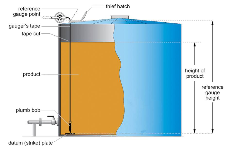
INNAGE Type - The datum line is at the bottom of the tank or
vessel. The measurement is taken IN the liquid from the
bottom to the surface of the liquid.
Innage Method
Innage Gauging
Innage gauging (also referred to as bottom gauging or dip gauging) measures
the distancefrom the datum (strike) plate (or the bottom of the tank if there
is no datum plate)to the surface of the product. An innage bob is used for innage gauging
Innage gauging is commonly used when:
1. tank contents are not viscous
2. the operator is able to lower the bob to the bottom of the tank
Advantage of innage gauging:
The height of the liquid in the tank is directly measured; the effects
reference gauge point movements are therefore eliminated. Innage gauging
is recommended whenever reference gauge point changes are suspected.
The operator can compare the tape reading at the reference gauge point
with the reference gauge height each time a tank is gauged and thus can
note any variances. (As a tank fills, the tank walls can expand; this expansion
result in movement of the reference gauge point and/or the datum plate.)
Disadvantages of innage gauging:
The tape may be lowered too far, causing the bob to tilt. Sedimentation on
the tank bottom may prevent the gauge from actually reaching the bottom
or may cause the bob to tilt In highly viscous products, the bob and tape may
tilt the gauging tape is immersed in the liquid and must be thoroughly cleaned
while the tape is being reeled in. In addition to being a messy and time-consuming
procedure,with corrosive or toxic products, cleaning the gauge tape exposes
the operator to health or safety hazards
OUTAGE OR ULLAGE Method:
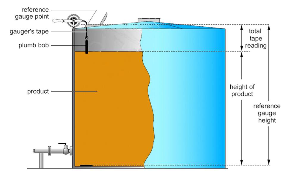
OUTAGE or ULLAGE Type - The datum line is at the top of the tank or vessel.
The measurement is taken OUT of the liquid from the top of the tank to
the surface of the liquid.
Outage gauging (also referred to as ullage gauging or top gauging) measures
of the tank less the gauge reading at the reference gauge point
the distance from the surface of the product in the tank to a reference gauge
point on the gauge hatch at the top of the tank. An outage bob is used for outage
gauging. Outage gauging is commonly used when the contents are corrosive or
toxic, extremely viscous or clear (such as water or gasoline)
The height of liquid must be calculated: height equals the reference gauge height
Advantage:
Only the bob is immersed in the liquid and cleanup is quick
Disadvantages:
The height of the liquid in the tank is indirectly measured:
The actual height must be calculated
The operator cannot observe any reference gauge point variances.
(Reference gauge point variances can only be seen with innage gauging
when the tape is lowered to the datum plate)
Outage gauging should only be used if the reference gauge
height does not vary with productlevel in the tank
Types of Level Measurement:
1. Continuous Level Measurement
2. Single-point Level Detection
Continuous Level Measurement:
Continuous Level Measurement
Provides continuous level measurements and give a numerical reading of level at all times.
This allows for constant monitoring of liquids that are important to plant operation.
Single-Point detection:
Single-Point Level Detection measures liquid level at a single point only.
It is used to detect either high or low level and provide on - off control for pumps and valves,
signal alarms, and initiate immediate corrective actions.
They can also be used to steps in an industrial process that occur repeatedly at given levels.
Magnetic Level Switches
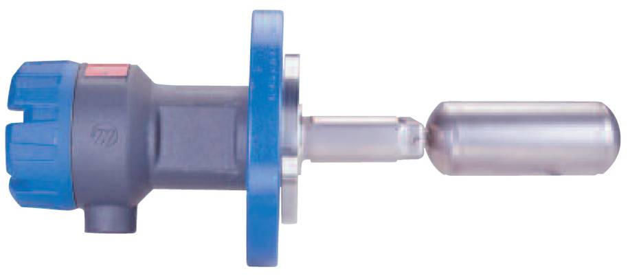
Magnetic Level Switch
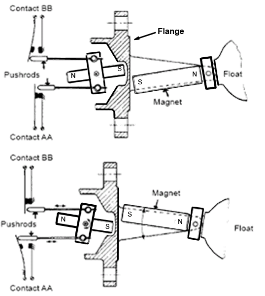
Magnetic level switches are used for on-off control. Float movement is transmitted through the process flange with magnets, sealing the contacts from the process fluid.
Ultrasonic Level Switch
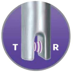
Contact ultrasonic level switches use ceramic discs called piezoelectric crystals to
transmit and receive ultrasonic energy. A transmit crystal (T) is positioned on one
side of a transducer gap and a receive crystal (R) is positioned on the opposite side.
Tip sensitive style gaps can sense level to within 1/4" from the end of the transducer.
Types of Level Measuring Instruments: Simple Instruments
1.Gauge Glasses
2. Manual Tank Gauging (Gauge Tape, Dipstick)
3. Floats and Displacers
4. Sonic and Radar
Simple Instruments: Gauge Tape
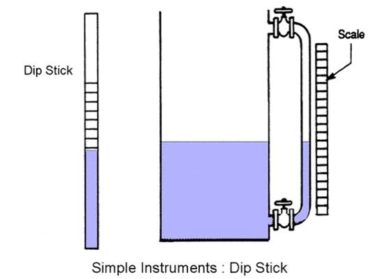
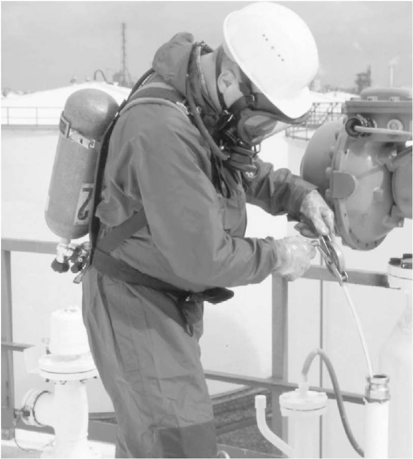
Manual Tank Gauging
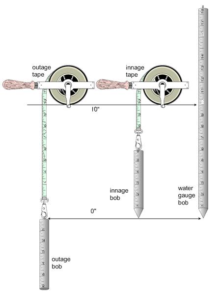
Gauge Tapes
Gauges consist of a bob attached to a steel gauging tape.
Gauging tapes are made of steel or corrosion-resistant material wound onto
a reel with a crank and a handle.The free end of the tape is equipped with
a snap hook for attachment of the bob.The graduations on gauging tapes
are specific for either outage gauging or innage gauging.The outage tape
ends at zero (at the point of contact between the snap hook and the bob eye)
the innage tape does not end at zero, the tip of the innage bob is the zero point.
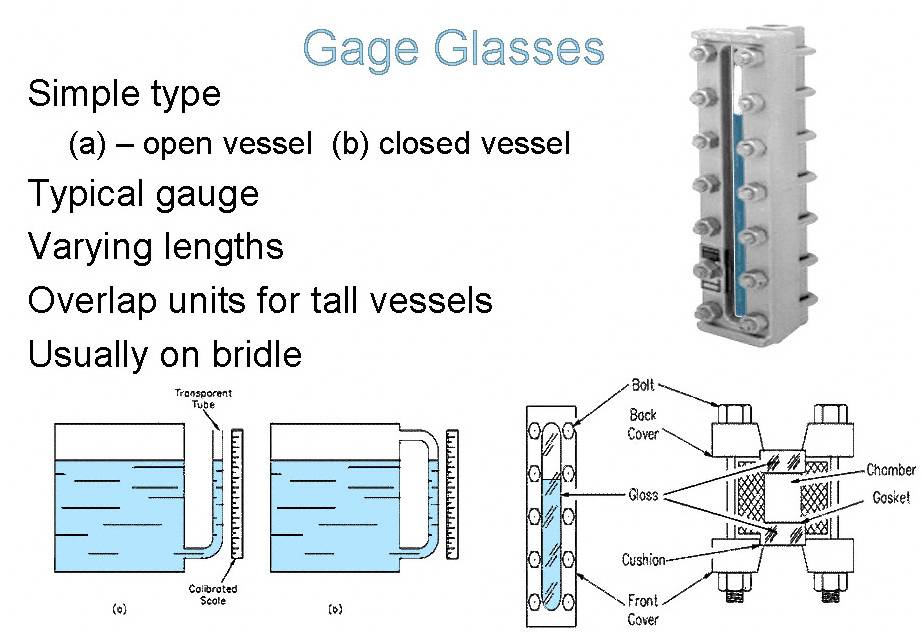
The pressure that the liquid exerts in the tank forces the liquid in the sight glass
to rise to the same level as the liquid in the tank.
Ball Float
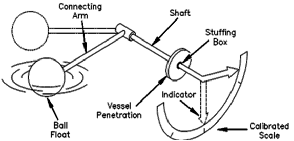
A ball float attached to a rod, which in turn is connected to a rotating shaft which
indicates level on a calibrated scale.
If the liquid level changes, the float will follow and change the position of the
pointer attached to the rotating shaft.
Float and tape operated Tank Gauge
Cone roof tank with Stilling Well
Floating Roof Tank and Floatwell
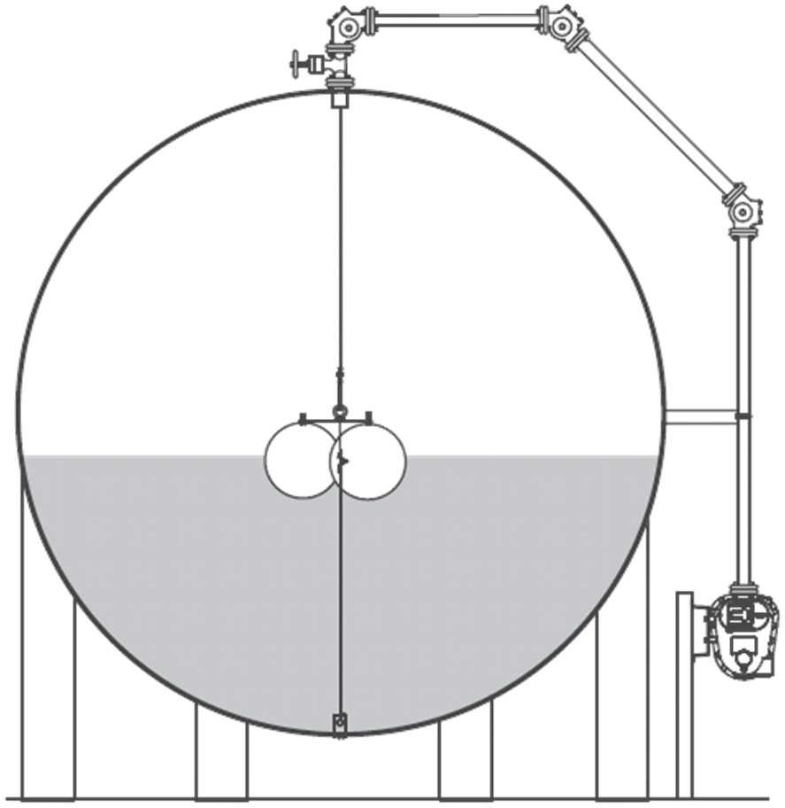
Sphere Tank
ATG flat hollow shell float MultiSphereFloat
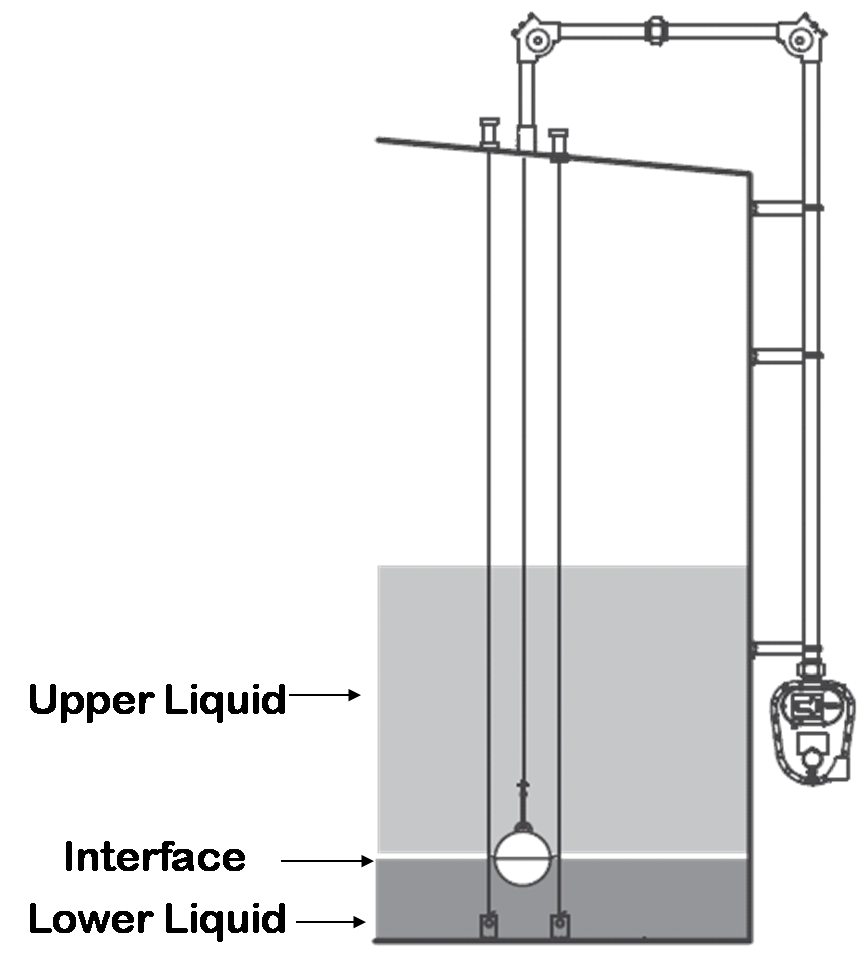
Interface Float 6"
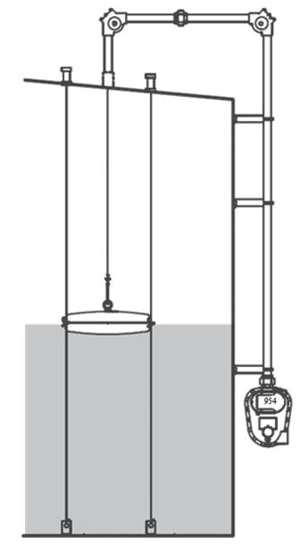
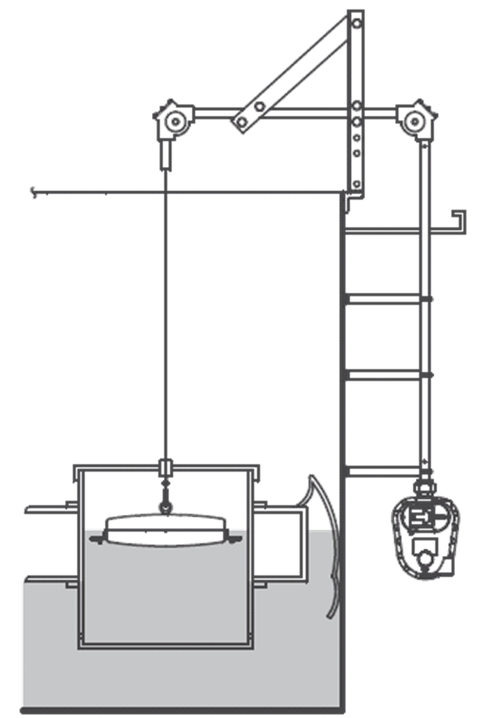
Servo Operated Displacer Level Gauge
The displacer is suspended from a strong and flexible measuring wire wound on a
measuring drum. A transducer measures the apparent weight of the displacer partly
immersed in liquid. When the level starts moving downwards, the transducer will
sense the change in weight. The servo motor drives the measuring drum to unwind
the measuring wire until the displacer is partly immersed in liquid. When the
level rises, the servo motor drives the measuring drum to wind up the measuring
wire until the displacer is again partly immersed in liquid
Servo Operated Level Gauge on a Spherical Tank

Ultrasonic / Sonic
The device measures the length of time it takes for the reflected sound wave to return to the transducer.
A successful measurement depends on reflection from the process material in a straight line back to the transducer.
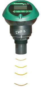
The ultrasonic transmitter is designed to be mounted above a liquid, and uses ultrasonic pulses to continuously measure the distance to the surface of the liquid. The microprocessor-controlled electronics calculates distance to the liquid level from the time delay between the transmitting and receiving of the signals
Good for interfaces, solids, slurries.
Advantages:
The main advantages of ultrasonic level instrumentation are that the transducer does
not come into contact with the process material.
They have no moving parts and a single top of vessel entry makes leaks less probable
than fully wetted techniques.
Disadvantages:
Things such as powders, heavy vapors, surface turbulence, foam and even ambient
noise can affect the returning signal also ultrasonic devices will not operate on vacuum
or high pressure applications.
Practical Notes
Successful measurement depends on the transmitter being mounted in the correct
position so that the internal structure of the vessel will not interfere with the signal path
The transducer transmits a sound burst and the echo is recorded as a signature of the tank.
Any obstructions in the vessel will send an echo and create a profile. Later on, this signature
or profile is locked into the ultrasonic unit’s memory so it will not respond
to echoes created by these obstructions.
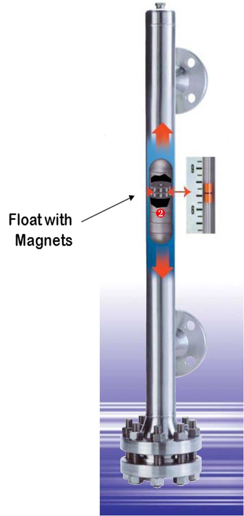
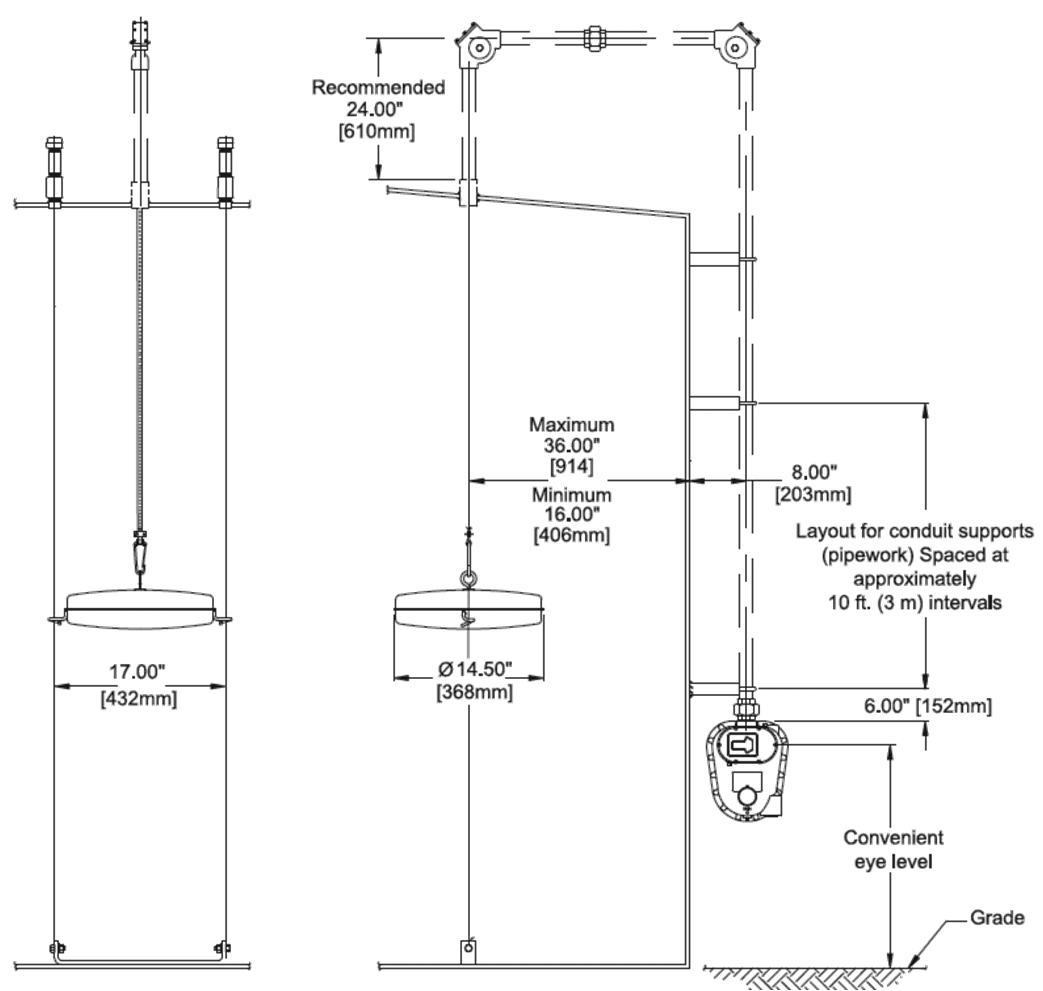
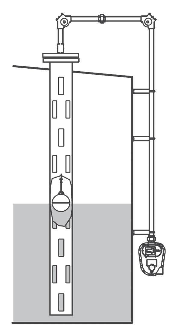
Magnetic Level Indicator
Principle of Operation
Within the piping column of the Magnetic Level Indicator is a float
containing an internal group of magnets. In response to the level movement
the float moves up or down accordingly.
Clamped to the piping column in total isolation from the process liquid
is a visual indicator which contains an alignment magnet which couples
with the float magnets as the float moves up or down within the piping column
The position of the visual indicator represents true level. Level is indicated or
by the corresponding point on the measuring scale.
Bubblers
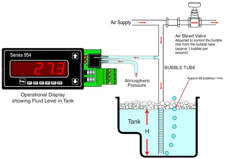
This simple level measurement has a dip tube installed with the open end closeto the bottom of the process vessel.A flow of gas, usually air or nitrogen passes through the tube and the resultant airpressure in the tube corresponds to the hydraulic head of the liquid in the vessel.The air pressure in the bubbler tube varies proportionally with the change inhead pressure.
Advantages:
Simplicity of design and low initial purchase cost are frequently given as advantages of bubblers. The regulator produces the constant gas flow required to prevent calibration changes.
Disadvantages:
Calibration is directly affected by changes in product density. It is frequently also necessary to periodically clean this device. The tip of the pipe can collect material from the process, solidify, and plug the hole.
Bubblers are not suitable for use in non-vented vessels.
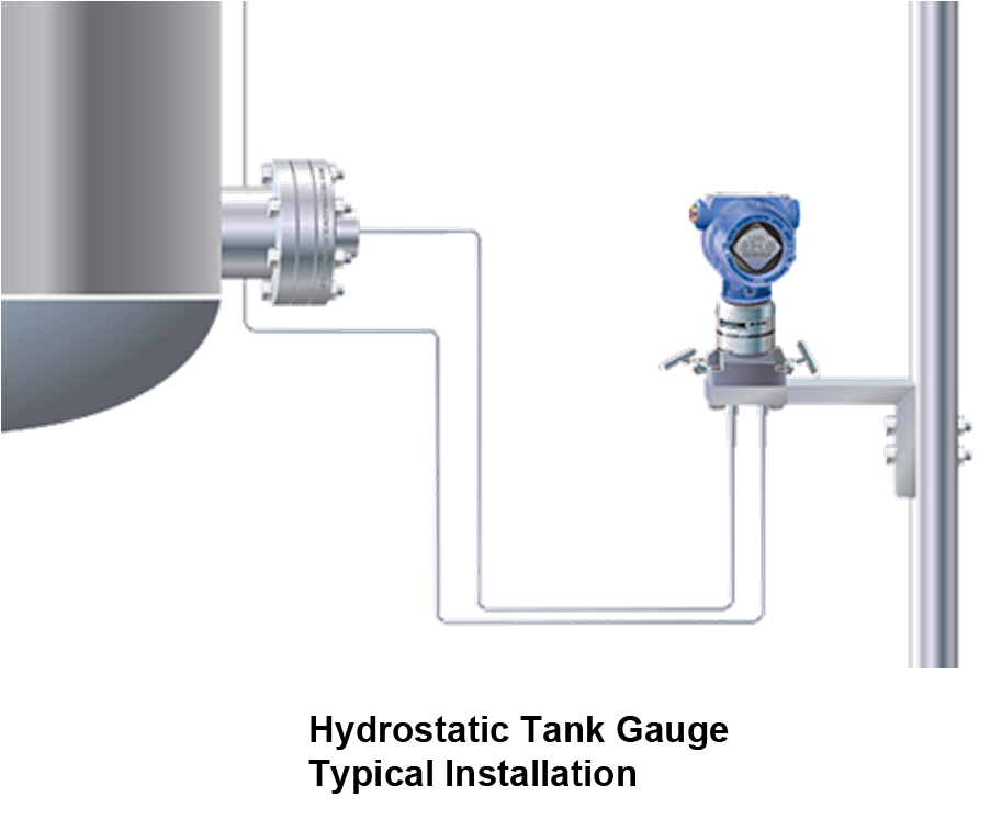
Hydrostatic Tank Gauging
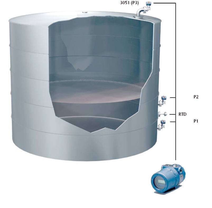
Level measurement based on pressure measurement is also referred to as hydrostatic
tank gauging (HTG).
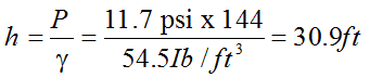
It works on the principle that the difference between the two pressures (d/p) equal
to the height of the liquid (h, in inches) multiplied by the specific gravity (SG) of the fluid(d/P = h (SG)
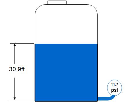
Example Problem
A pressure gauge located at the base ofan open tank containing a liquid with a
density of 54.5lb/ft3 registers 11.7psi. What is the depth of the fluid in the tank?
Elevation &Suppression
If the d/p cell is not located at an elevation that corresponds to 0% level in the tank,
it must be calibrated to account for the difference in elevation.This calibration
adjustment is called zero elevation when the cell is located above the tapping point,
and is called zero suppression when the cell is located below the tapping point.
Zero Suppression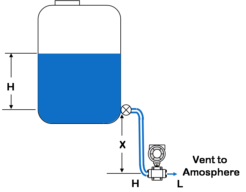
That is, the pressure on the high pressure side of the d/P cell is always higher than the actual pressure exerted by the liquid column in the tank by (SG . X) – so the reading will be in error high.
This constant pressure would cause an output signal that is higher than 4 mA when the tank is empty and above 20 mA when it is full.The transmitter has to be negatively biased by a value of SG. X so that the output of the transmitter is proportional to the tank level (SG . H) only.
This procedure is called Zero Suppression and is done during calibration of the transmitter.
When the liquid level is at H meters, pressure on the high pressure side of the transmitter will be:
Phigh = SG . H + SG . X + Patm
Plow= Patm
DP = Phigh - Plow = SG . H + SG . X
Zero suppression calculation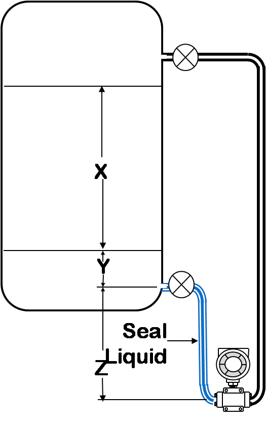
Span = (x) (GL)
HW at minimum level = (z) (GS) + (y) (GL)
HW at maximum level = (z) (GS) + (x + y) (GL)
Where
GL = Specific gravity of tank liquid
GS = Specific gravity of seal liquid
HW = Equivalent head of water
x, y, and z as shown
Example:
Open tank with x = 80 inches
y = 5 inches
z = 10 inches
GL = 0.8
GS = 0.9
Span = (80)(0.8) = 64 inches
HW at minimum level = (10)(0.9) + (5)(0.8) = 13 inches
HW at maximum level = (10)(0.9) + (5 + 80)(0.8) = 77inches
Calibrated Range = 13 to 77 inches head of water
Zero Elevation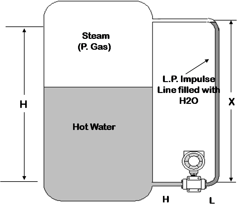
When a wet leg installation is used,the low pressure side of the level transmitter will always experience a higher hydrostatic pressure than the high pressure side.
This is due to the fact that the height of the wet leg (X) is always just greater than the maximum height of the liquid column (H) inside the tank.
When the liquid level is at H meters, we have:
The differential pressure DP sensed by the transmitter is always a negative value (i.e. the low pressure side has a higher pressure than high pressure side).
Zero elevation calculation Closed Tank With Wet Leg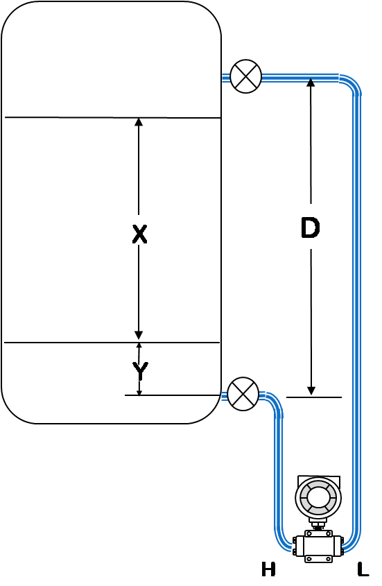
Span = (x)(GL) Wet Leg
HW at minimum level = (y)(GL) - (d)(GS)
HW at maximum level = (x + y)(GL) - (d)(GS)
Where
GL = Specific gravity of tank liquid
GS = Specific gravity of seal liquid
HW = Equivalent head of water
Example:
Closed tank with x = 70 inches y = 20 inches,
and d = 100 inches
GL = 0.8 Seal Liquid
GS = 0.9
Span = (70)(0.8) = 56 inches
HW at minimum level = (20)(0.8) - (100)(0.9) = -74 inches<
HW at maximum level = (70 + 20)(0.8) - (100)(0.9) = -18 inches
Calibrated Range = -74 to -18 inches head of water
(Minus signs indicate that the higher pressure is applied to the
low pressure side of the transmitter.)
Interface Measurement
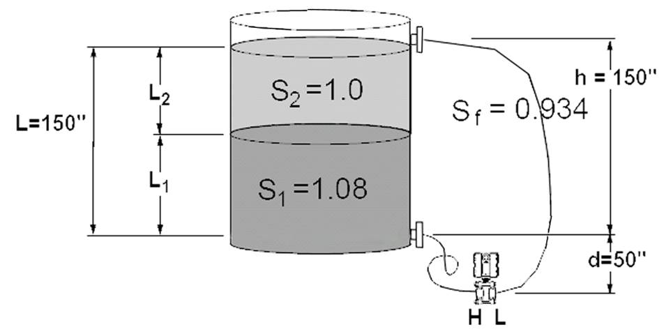
Differential pressure (DP)transmitters are used to measure the interface of two fluids that have different
specific gravities (S).
An interface measurement where the level is 150 inches and fluids with specific gravities of 1.0 and 1.08
Four assumptions need to be made:
1. At the 4 mA point, the tank is filled with the lighter fluid.
2. At the 20 mA point, the tank is filled with the heavier fluid.
3. The taps leading to the transmitter are flooded at all times.
The over all level should be equal to or higher than the upper (low pressure)tap
4. There is always a reference level seen by the low pressure side.
This can be accomplished with either a remote seal system or a wet leg.
The reference level must have a constant height and density.
The measuredl evel is composed of a combination of the two fluids:
L = L1S1 + L2S2
When the tank is filled with the lighter fluid, the transmitter will be at
4 mA (or 0% of span)and L2 = L
HP = L2S2 + dSf
LP = dSf + hSf
4mA DP = HP – LP = L2S2 – hSf
DP = (150 x 1.0) – (150 x 0.934)
4mA = 9.9 inH2O
When the tank is filled with the heavier fluid,the transmitter will be at
20 mA (or 100% of span) and L1 = L
HP = L1S1 + dSf
LP = dSf + hSf
20mA DP = HP – LP = LS1 – hSf 20
DP = (150 x 1.08) – (150 x 0.934)
20mA = 21.9 inH2O The calibrated span is 9.9 to 21.9 inH2O.
When the transmitter reads 9.9 inH20, the tank is filled with the lighter fluid.
When the transmitter reads 21.9 inH20, the tank is filled with the heavier fluid.
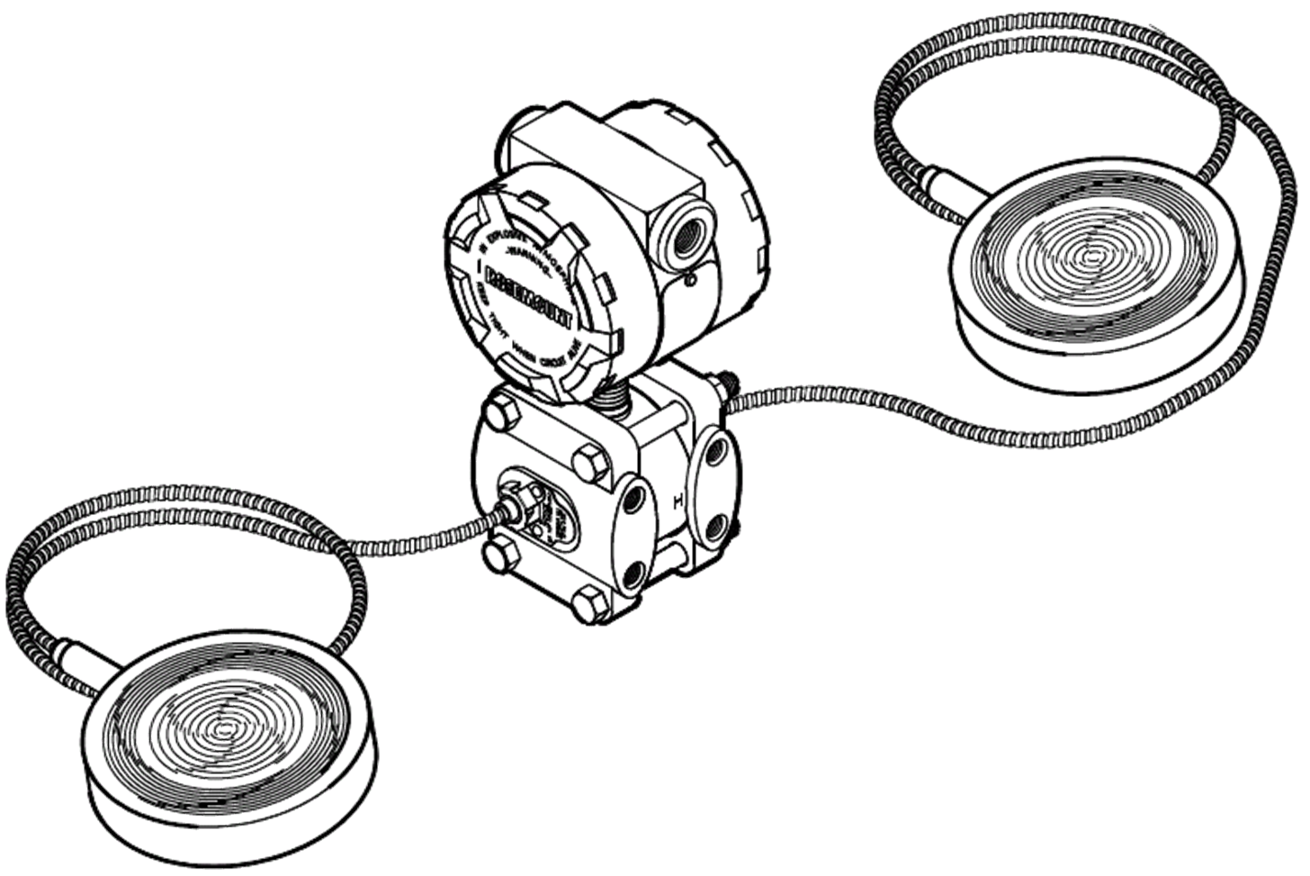
Diaphgram Seal dP transmitter
3-Valve Manifold Xmitter Connections
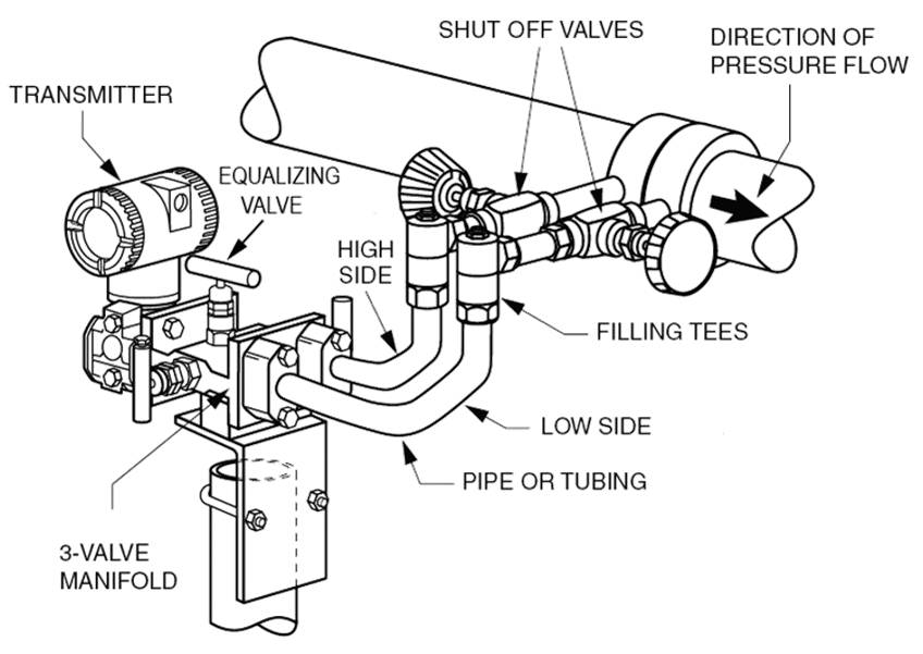
The 3 valve manifold is Used to enable the transmitter to be calibrated in place or removed
Operational Sequence of Three-Valve Manifold -putting a d/P Transmitter Out Of Service
The starting operating state is with the equalizing valve closed and both block valves open.
1. Close the low pressure block valve to trap pressure in the low side
check for leaks and ensure the indicated d/P does not change.
2. Open the equalizing valve to force d/P to zero.
3. Close the high pressure block valve to isolate the transmitter.
4. Bleed down (i.e. vent) the pressure trapped in the d/P cell body.
it should continue to read zero d/P
5. The d/P transmitter is now out-of-service, isolated and depressurized.
Operational Sequence of Three-Valve Manifold -putting a d/P Transmitter Into Service
To put the DP transmitter into service, the following steps should be followed:
1. Check all valves closed.
2. Open the equalizing valve- this ensures that the same pressure will be applied
to both sides of the transmitter, i.e.zero differential pressure.
3. Open the High Pressure block valve slowly, check for leakage from both the high
pressure and low pressure side of the transmitter – still zero d/P.
4. Close the equalizing valve - this locks the pressure on both sides of the transmitter
now look for leaks, should still be zero d/P.
5. Open the low pressure block valve to apply the process pressure to the low
pressure side of the transmitter and establish the working differential pressure.
6. The transmitter is now in service
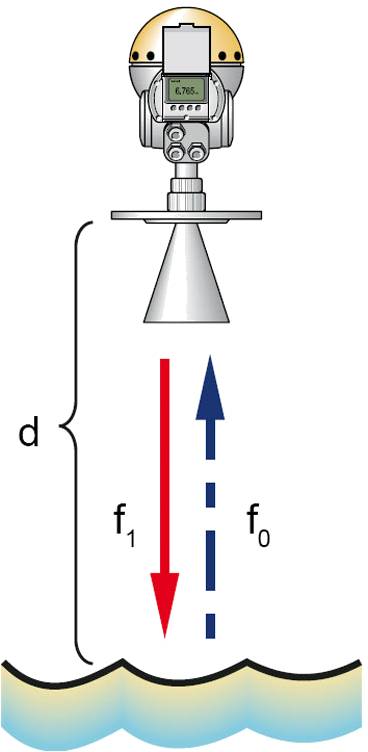
Radar
Radar instruments operate by transmitting a
high-frequency (GHz) electromagnetic radiation and
timing the transit time to the level surface and back.
There are two technologies; frequency modulated
continuous wave (FMCW)and pulsed wave time of flight.
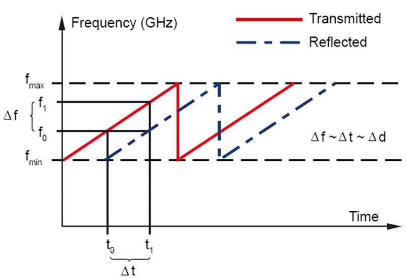
FMCW
The radar signal is reflected by the liquid surface and picked up by the antenna.
As the signal is varying infrequency the echo has a slightly different frequency compared to the signal transmitted at that moment.
The difference in frequency is proportional to the distance to the liquid,and can be accurately calculated. This method is called FMCW (FrequencyModulated Continuous Wave)
Time-of flight
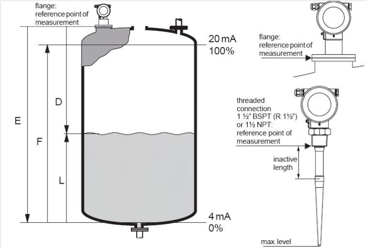
The time-of flight method measures the distance from the reference point (process connection) to the product surface. Radar impulses are emitted by an antenna, reflected off the product surface and received again by the radar system.
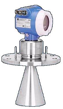
Radar Antenna
Advantages
This non-contact technology produces highly accurate measurements in storage tanks and some process vessels.
Radar can be highly accurate, is immune to most vapours/
physical characteristics of the measured media
Disadvantages
It’s primary disadvantage is cost, which can be justified for tank gauging and inventory control.The pressure ratings on radar antenna are limited and these devices cannot measure interfaces.
Practical Notes
Some installations, such as floating roof tanks, require the installation
of a still pipe. Inconsistencies on the internal surface of the still pipe
can cause erroneous echoes, these can have an adverse effect on the
accuracy of some vendor's equipment.
In the case of hydrocarbons, an accurate water bottoms measurement
must be made for preciseinventory control.
Displacers / Float
Float devices operate on the buoyancy Principle, as liquid level changes a sealed container will,providing its density is lower than that of the liquid,move correspondingly.
Displacers work on the Archimedes Principle, when abody is immersed in a fluid it loses weight equal tothat of the fluid displaced. By detection of the apparent weight of the immersed displacer, a level measurement can be inferred
Displacers and floats should only be used for relatively non-viscous,clean fluids.
Displacers and floats provide optimal performance in switch
applications and over for short spans
Advantages
Both floats and displacers work well with clean liquids and
are accurate and adaptable to wide variations in fluid densities.
Disadvantages
Displacers are affected by changes in product density.
Because the displacer is immersed in the process fluid it will be vulnerable to particulate deposition.This will change the displacer mass and the effective
displacement causing a calibration shift.
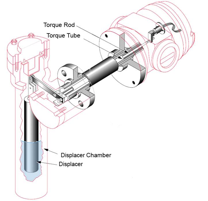 A change in liquid level
varies the net weight of the
displacer, increasing or decreasing the load on the
torque tube by an amount directly proportional
to the change in liquid level. The resultant rotation
of the torque rod is converted to an analog
4 to 20mA or pneumatic signal
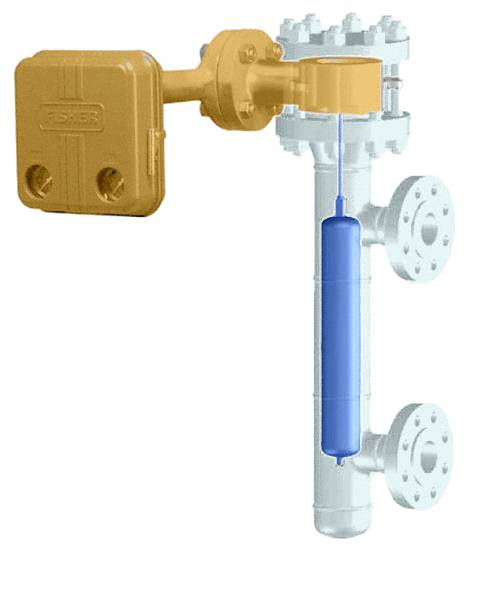
Masoneilan 3000 Level Controller/Transmitter
Most commonly used Local Level Controller.
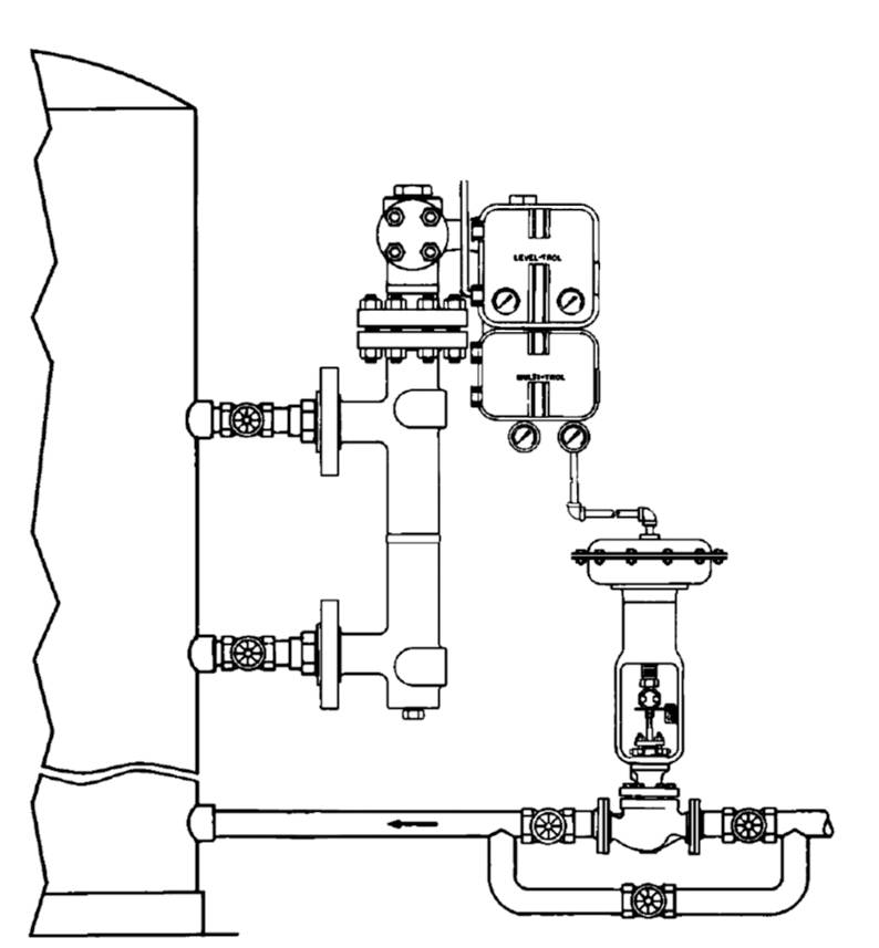 Self contained transmitter and controller
Limited control range
Level Sensor Selection
Questions that must be answered
Can the level sensor be inserted into the tank or
should it be completely external?
Should the sensor detect the level continuously or
will a point sensor be adequate?
Can the sensor come in contact with the process fluid or
must it be located in the vapor space?
Is direct measurement of the level needed or
is indirect detection of hydrostatic head
(which responds to changes in both level and density)acceptable?
Is tank depressurization or process shut-down
acceptable when sensor removal or maintenance is required?
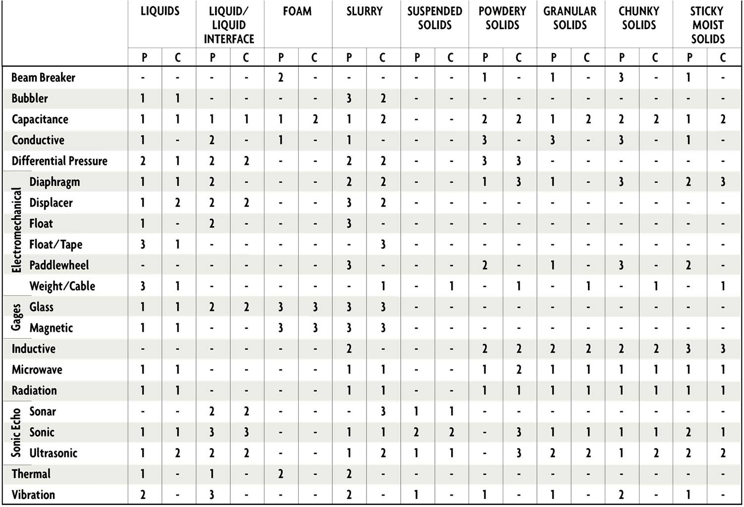
Applicability of Level Sensors
email: calmansys@yahoo.com